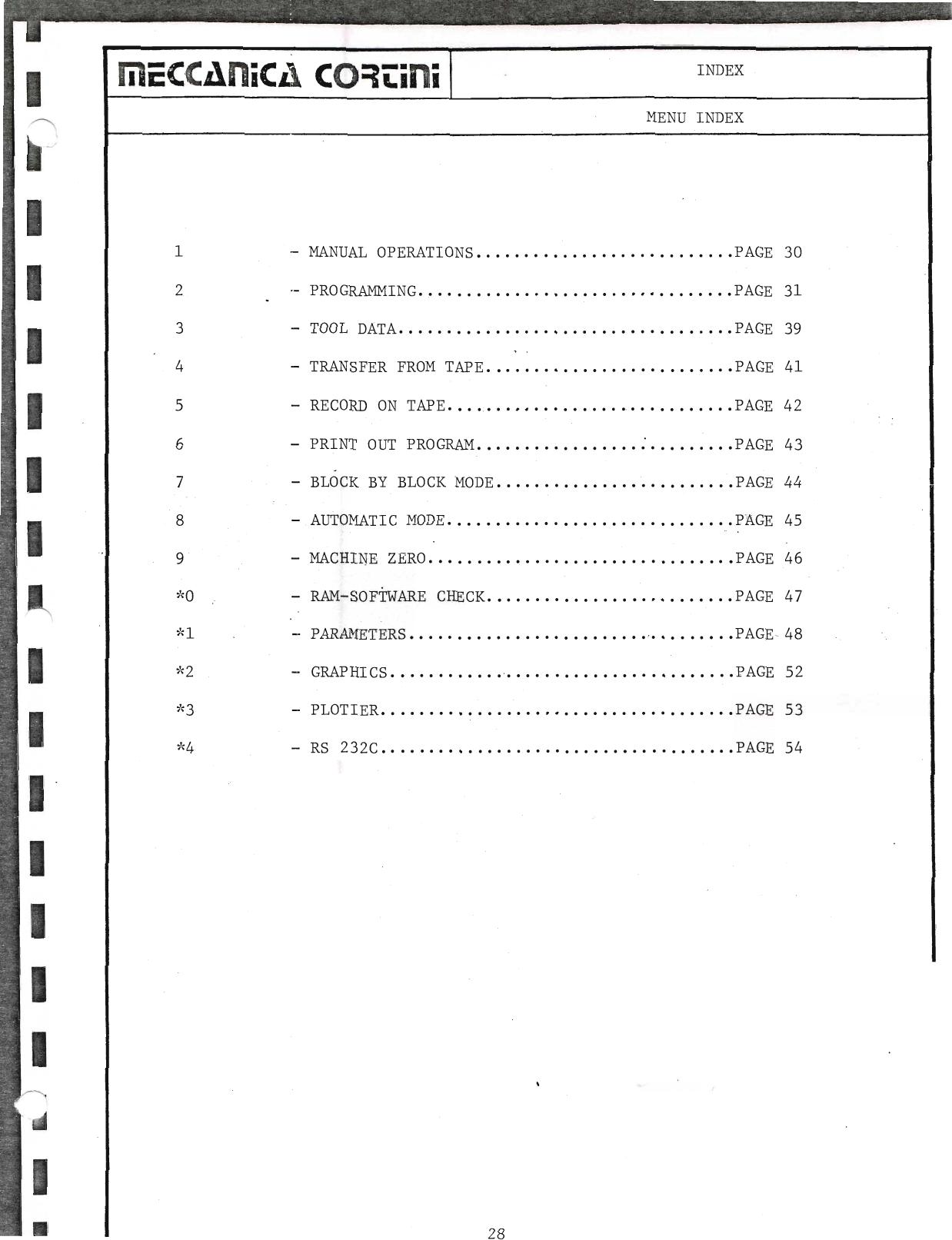
6.0 Main Menu
Switch-On
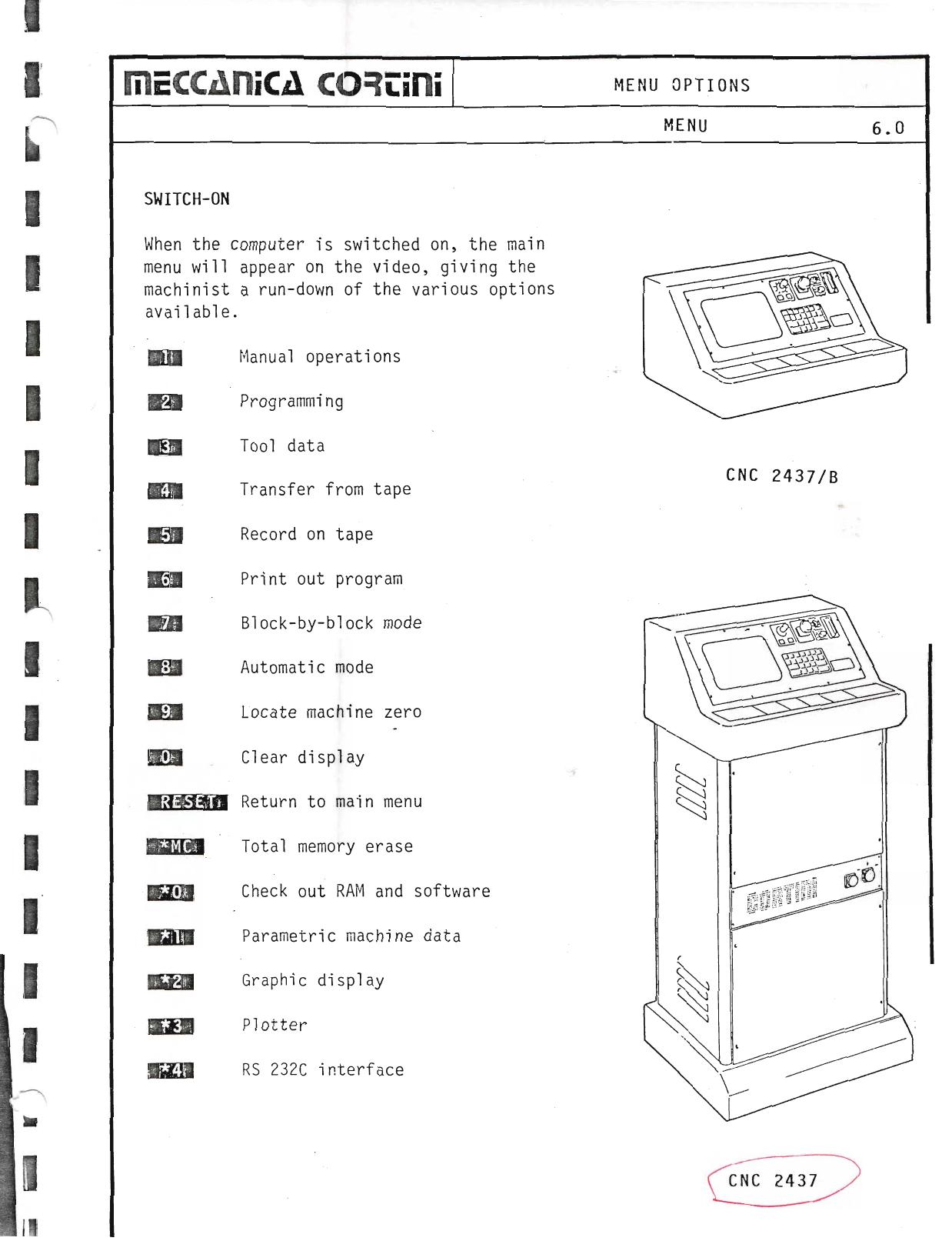
When the computer is switched on, the main menu will appear on the video, giving the machinist a run-down of the various options available.
| Key | Menu Option |
|---|
| 1 | Manual operations |
| 2 | Programming |
| 3 | Tool data |
| 4 | Transfer from tape |
| 5 | Record on tape |
| 6 | Print out program |
| 7 | Block-by-block mode |
| 8 | Automatic mode |
| 9 | Locate machine zero |
| 0 | Clear display |
| RESET | Return to main menu |
| MC | Total memory erase |
| *0 | Check out RAM and software |
| *1 | Parametric machine data |
| *2 | Graphic display |
| *3 | Plotter |
| *4 | RS 232C interface |
▶ Source — Page 047
![Original scan page 047]()
6.1 Manual Operations
6.1 Manual Positioning Video Page
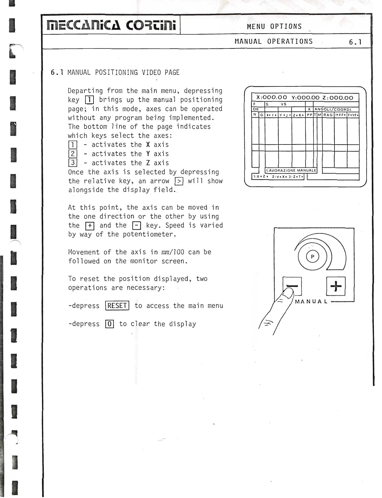
Departing from the main menu, depressing key 1 brings up the manual positioning page; in this mode, axes can be operated without any program being implemented.
The bottom line of the page indicates which keys select the axes:
- Activates the X axis
- Activates the Y axis
- Activates the Z axis
Once the axis is selected by depressing the relative key, an arrow will show alongside the display field.
At this point, the axis can be moved in the one direction or the other by using the + and the − key. Speed is varied by way of the potentiometer.
Movement of the axis in mm/100 can be followed on the monitor screen.
To reset the position displayed, two operations are necessary:
- Depress RESET to access the main menu
- Depress 0 to clear the display
▶ Source — Page 048
![Original scan page 048]()
6.2 Programming Page
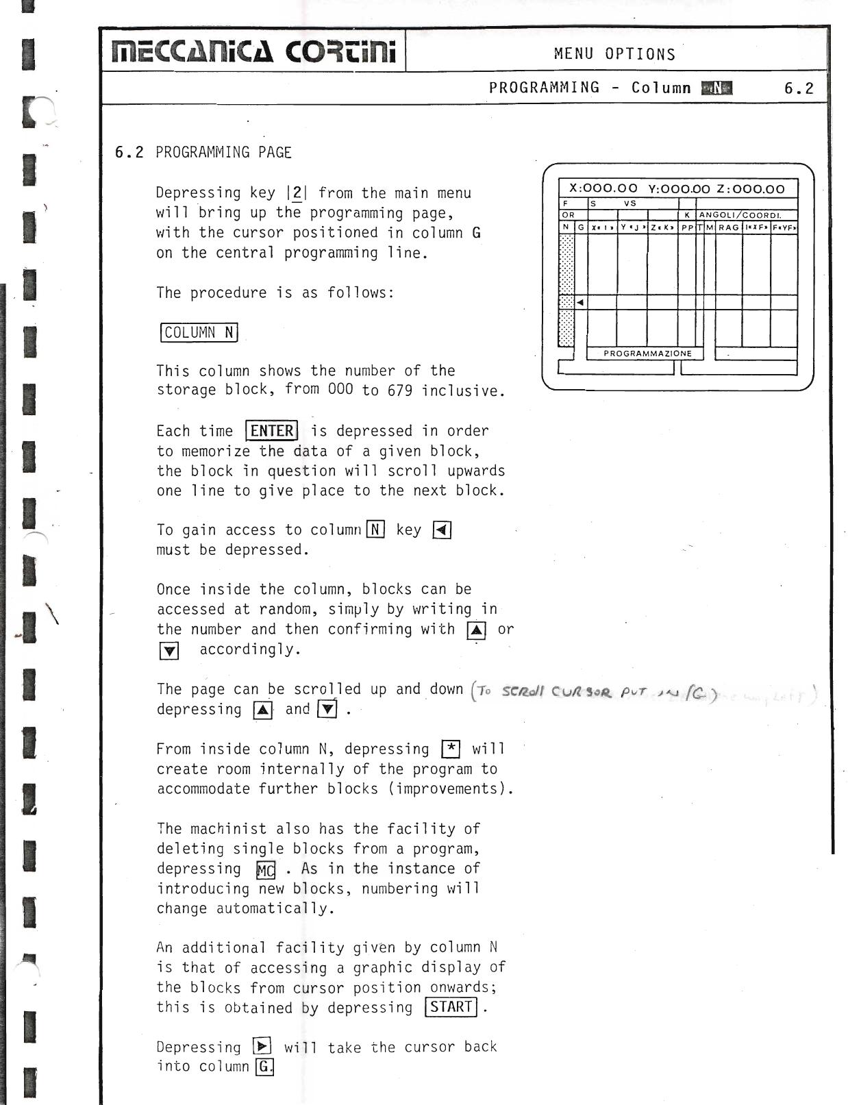
Depressing key 2 from the main menu will bring up the programming page, with the cursor positioned in column G on the central programming line.
Column N
This column shows the number of the storage block, from 000 to 679 inclusive. Each time ENTER is depressed in order to memorize the data of a given block, the block in question will scroll upwards one line to give place to the next block.
To gain access to column N, key N must be depressed. Once inside the column, blocks can be accessed at random, simply by writing in the number and then confirming with ↑ or ↓ accordingly.
The page can be scrolled up and down by depressing ↑ and ↓.
From inside column N, depressing INS will create room internally of the program to accommodate further blocks (improvements). The machinist also has the facility of deleting single blocks from a program by depressing DEL. As in the instance of introducing new blocks, numbering will change automatically.
An additional facility given by column N is that of accessing a graphic display of the blocks from cursor position onwards; this is obtained by depressing START. Depressing G will take the cursor back into column G.
▶ Source — Page 049
![Original scan page 049]()
Column G & G-Functions
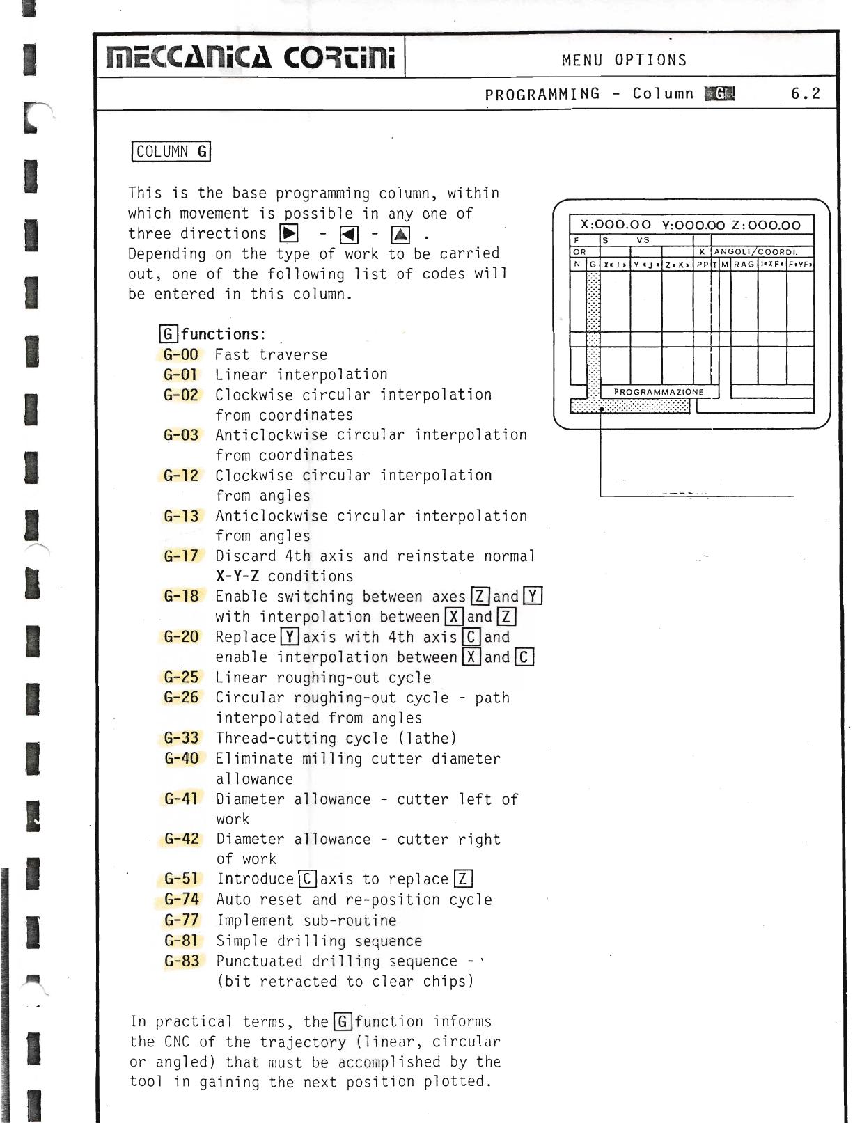
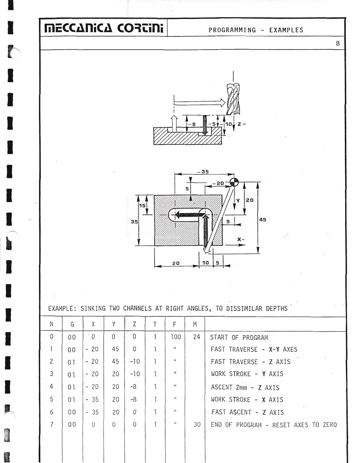
This is the base programming column, within which movement is possible in any one of three directions → ← ↑/↓. Depending on the type of work to be carried out, one of the following list of codes will be entered in this column.
G-functions:
| Code | Function |
|---|
| G-00 | Fast traverse |
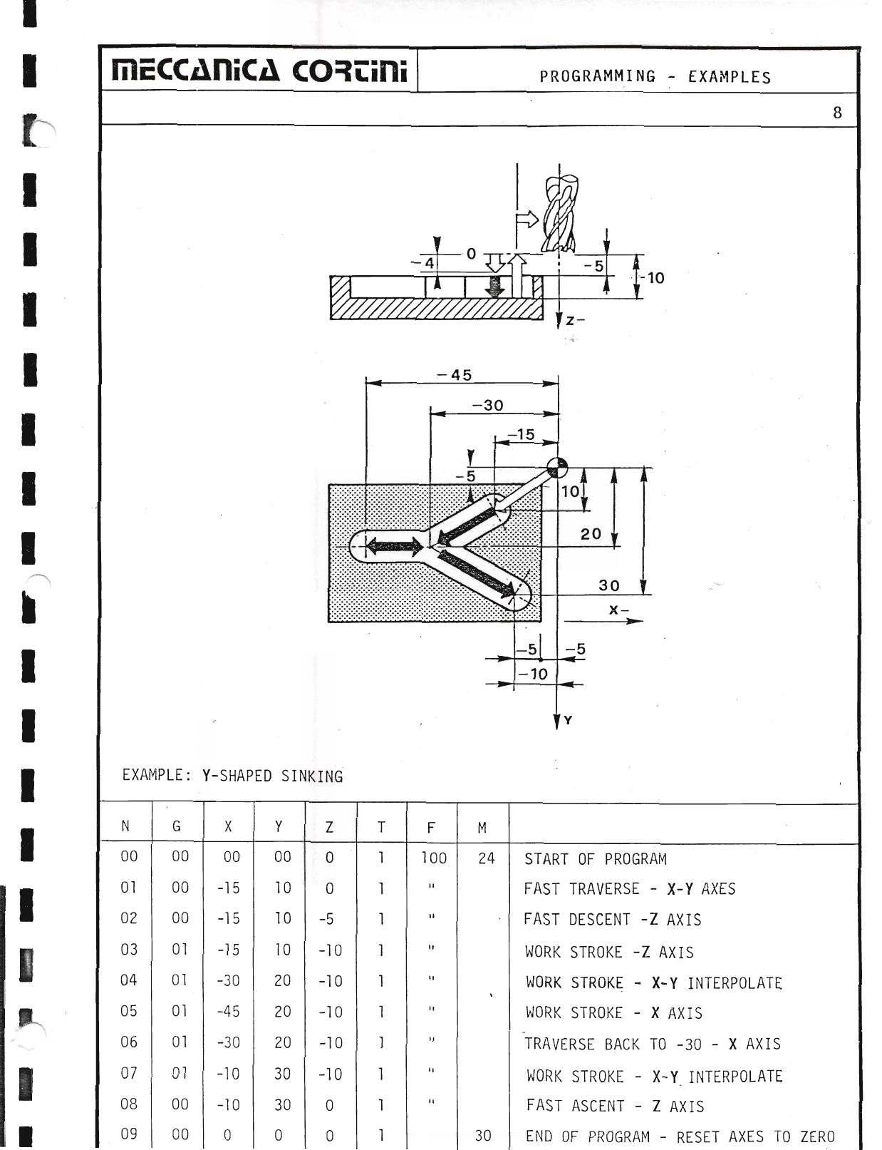
| G-01 | Linear interpolation |
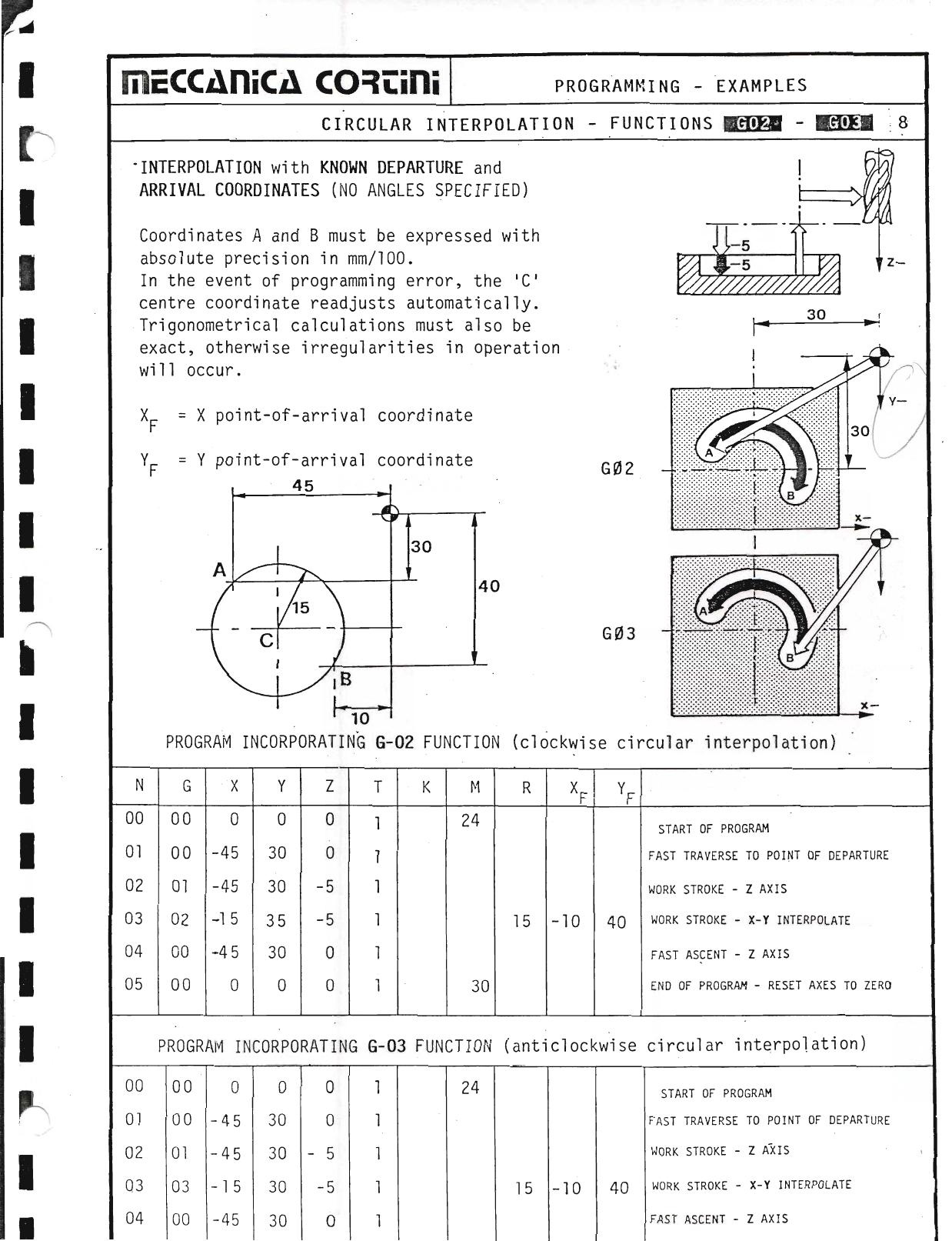
| G-02 | Clockwise circular interpolation from coordinates |
| G-03 | Anticlockwise circular interpolation from coordinates |
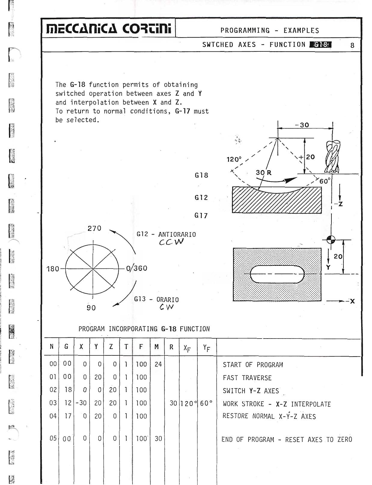
| G-12 | Clockwise circular interpolation from angles |
| G-13 | Anticlockwise circular interpolation from angles |
| G-17 | Discard 4th axis and reinstate normal X-Y-Z conditions |
| G-18 | Enable switching between axes Z and Y with interpolation between X and Z |
| G-20 | Replace Y axis with 4th axis C and enable interpolation between X and C |
| G-25 | Linear roughing-out cycle |
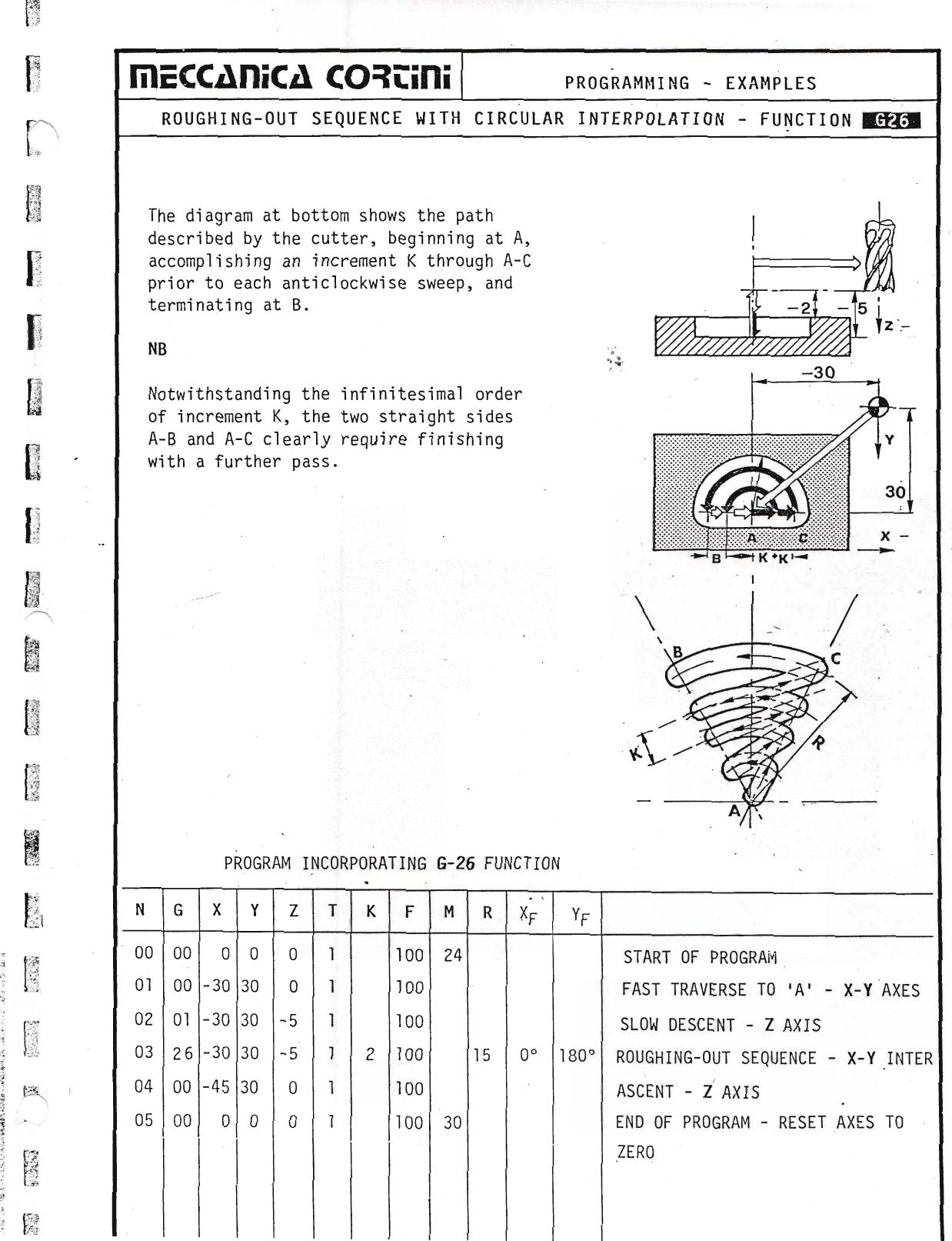
| G-26 | Circular roughing-out cycle — path interpolated from angles |
| G-33 | Thread-cutting cycle (lathe) |
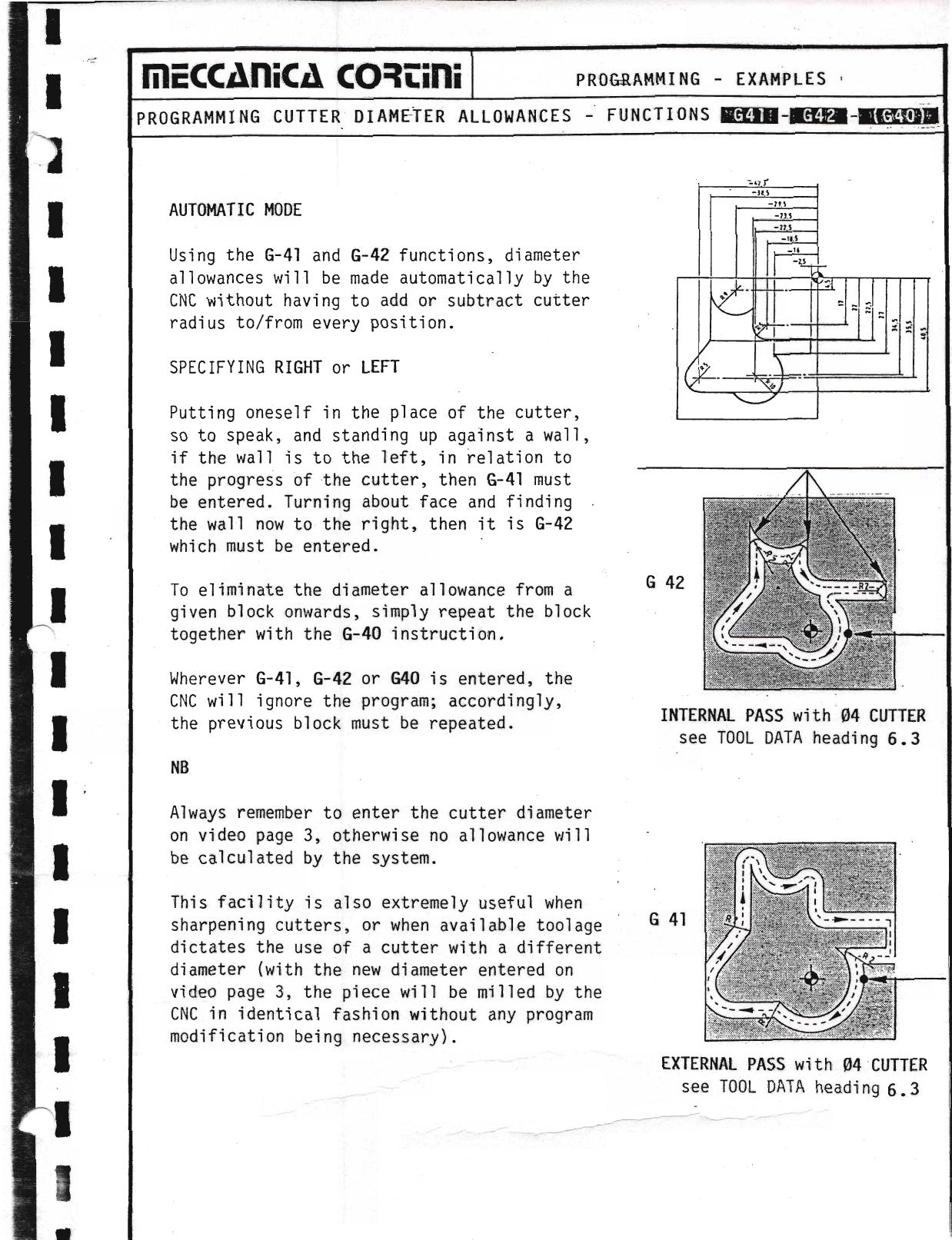
| G-40 | Eliminate milling cutter diameter allowance |
| G-41 | Diameter allowance — cutter left of work |
| G-42 | Diameter allowance — cutter right of work |
| G-51 | Introduce C axis to replace Z |
| G-74 | Auto reset and re-position cycle |
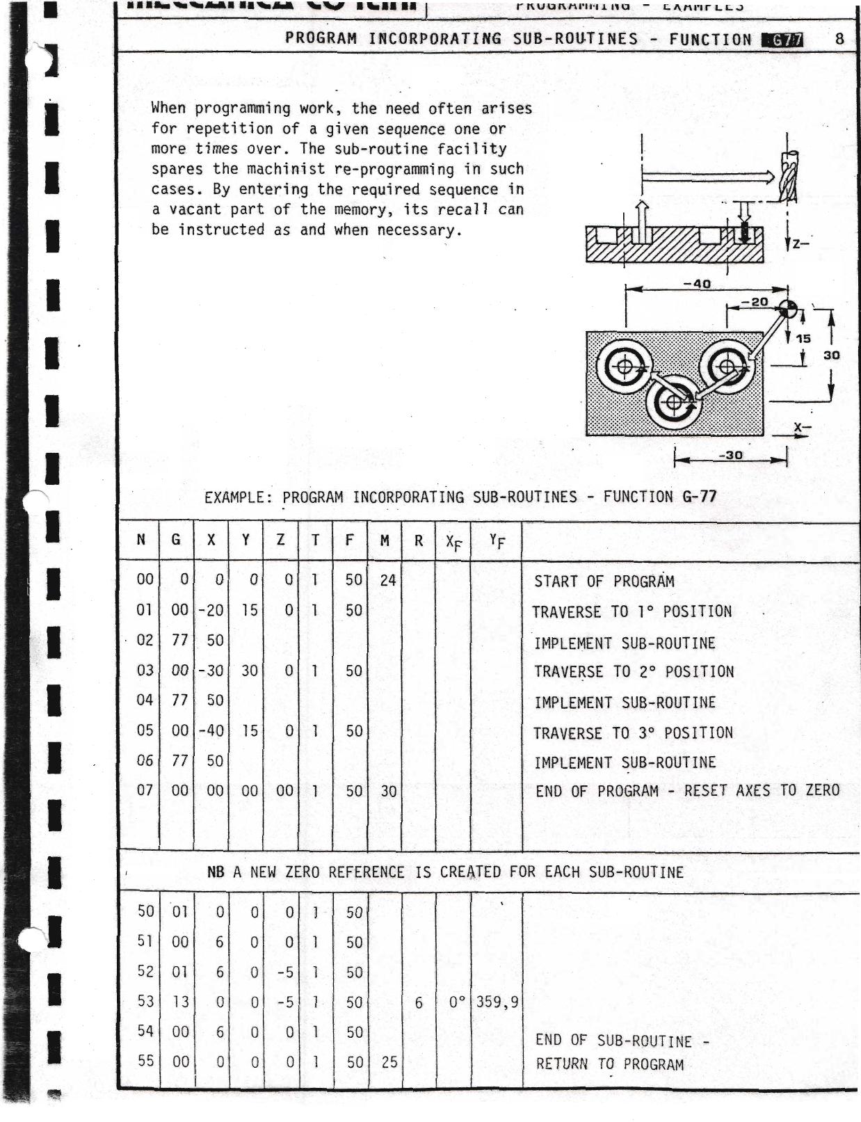
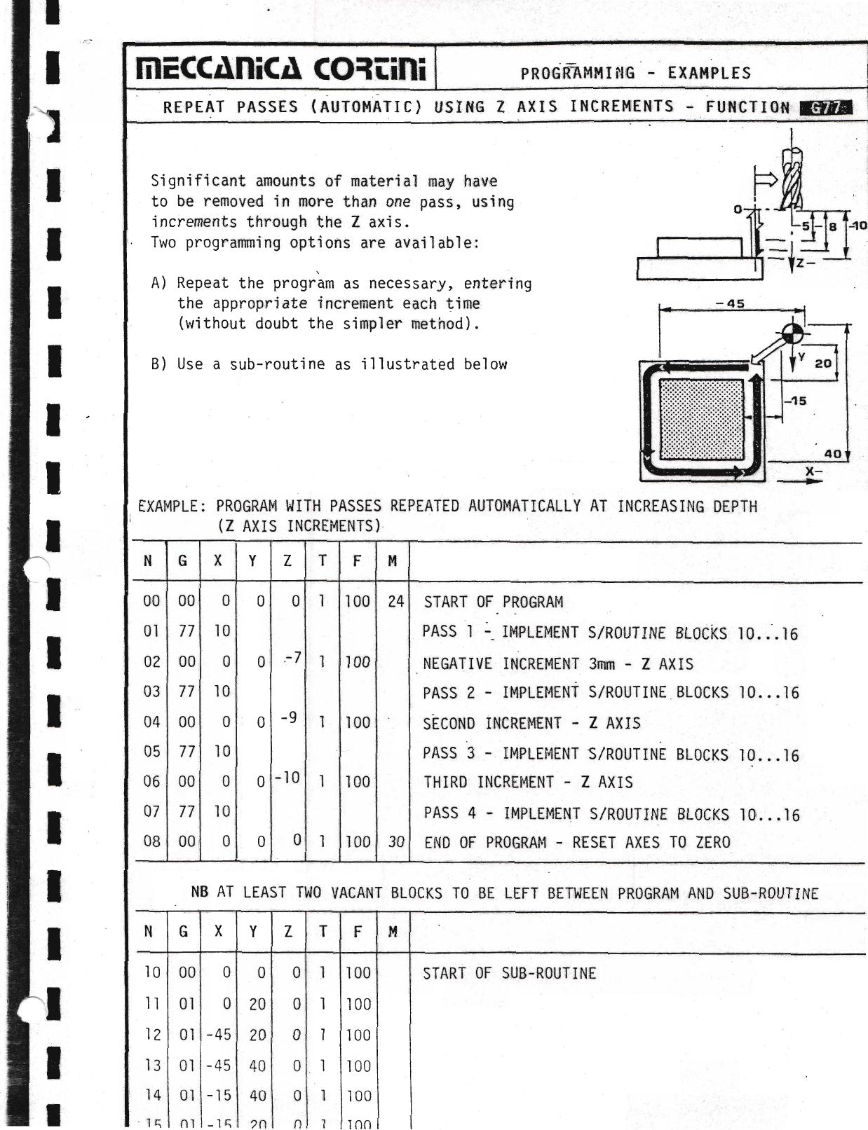
| G-77 | Implement sub-routine |
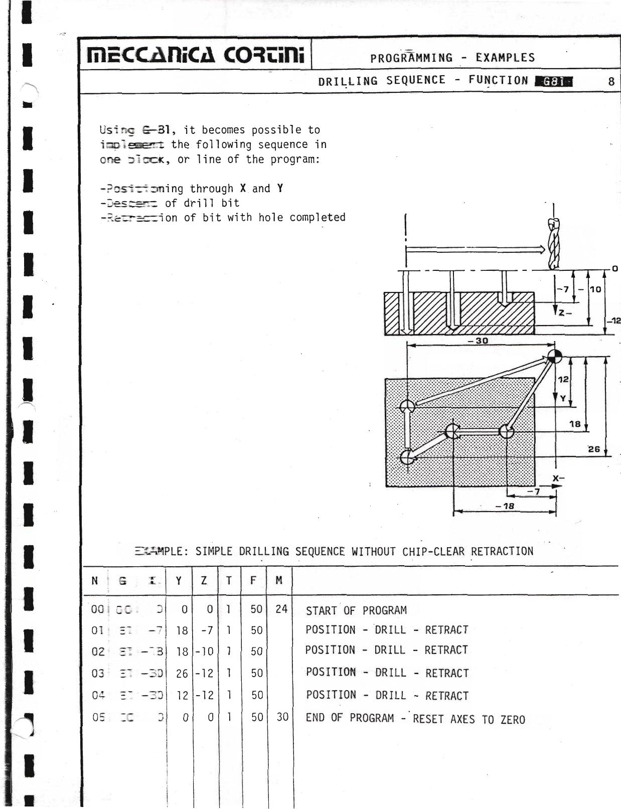
| G-81 | Simple drilling sequence |
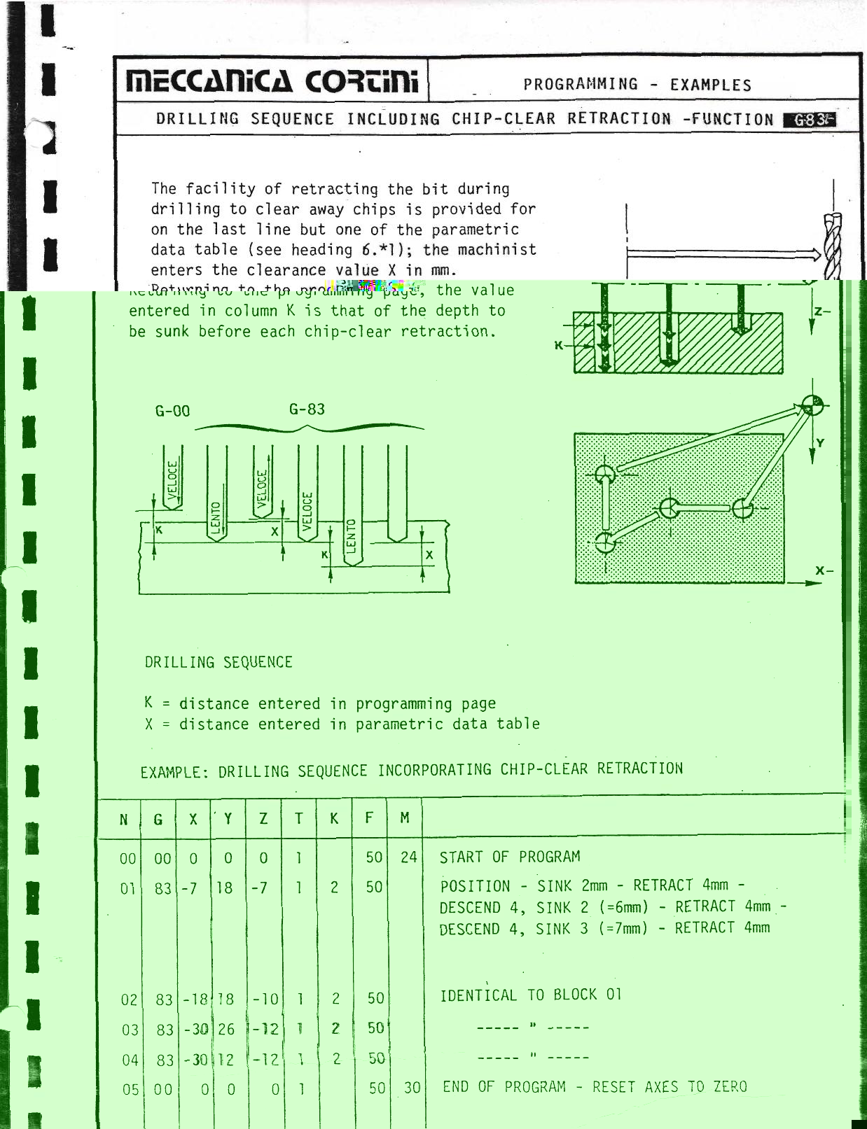
| G-83 | Punctuated drilling sequence (bit retracted to clear chips) |
In practical terms, the G function informs the CNC of the trajectory (linear, circular or angled) that must be accomplished by the tool in gaining the next position plotted.
Column G is the only area of the program page from which the START instruction can be given to the L300.
▶ Source — Page 050
![Original scan page 050]()
Column X
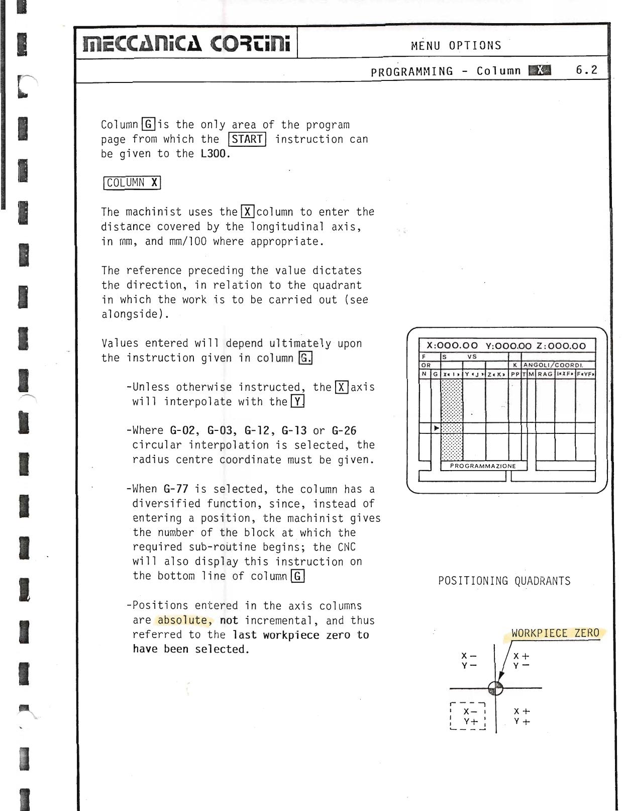
The machinist uses the X column to enter the distance covered by the longitudinal axis, in mm, and mm/100 where appropriate. The reference preceding the value dictates the direction, in relation to the quadrant in which the work is to be carried out.
Values entered will depend ultimately upon the instruction given in column G:
- Unless otherwise instructed, the X axis will interpolate with the Y axis.
- Where G-02, G-03, G-12, G-13 or G-26 circular interpolation is selected, the radius centre coordinate must be given.
- When G-77 is selected, the column has a diversified function: instead of entering a position, the machinist gives the number of the block at which the required sub-routine begins; the CNC will also display this instruction on the bottom line of column G.
- Positions entered in the axis columns are absolute, not incremental, and thus referred to the last workpiece zero to have been selected.
▶ Source — Page 051
![Original scan page 051]()
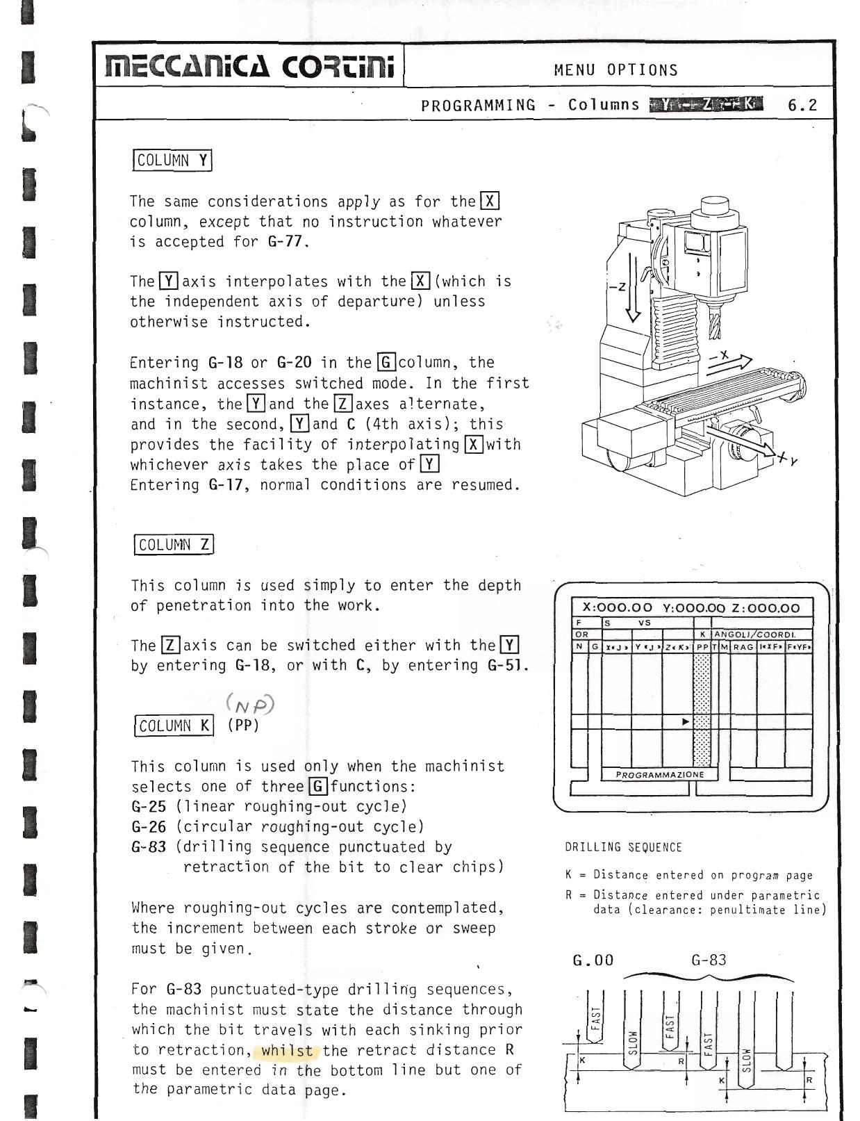
Column Y
The same considerations apply as for the X column, except that no instruction whatever is accepted for G-77.
The Y axis interpolates with the X (which is the independent axis of departure) unless otherwise instructed.
Entering G-18 or G-20 in the G column, the machinist accesses switched mode. In the first instance, the Y and the Z axes alternate, and in the second, Y and C (4th axis); this provides the facility of interpolating X with whichever axis takes the place of Y. Entering G-17, normal conditions are resumed.
Column Z
This column is used simply to enter the depth of penetration into the work. The Z axis can be switched either with the Y by entering G-18, or with C by entering G-51.
Column K
This column is used only when the machinist selects one of three G-functions:
- G-25 (linear roughing-out cycle)
- G-26 (circular roughing-out cycle)
- G-83 (drilling sequence punctuated by retraction of the bit to clear chips)
Where roughing-out cycles are contemplated, the increment between each stroke or sweep must be given.
For G-83 punctuated-type drilling sequences, the machinist must state the distance through which the bit travels with each sinking prior to retraction, whilst the retract distance R must be entered in the bottom line but one of the parametric data page.
▶ Source — Page 052
![Original scan page 052]()
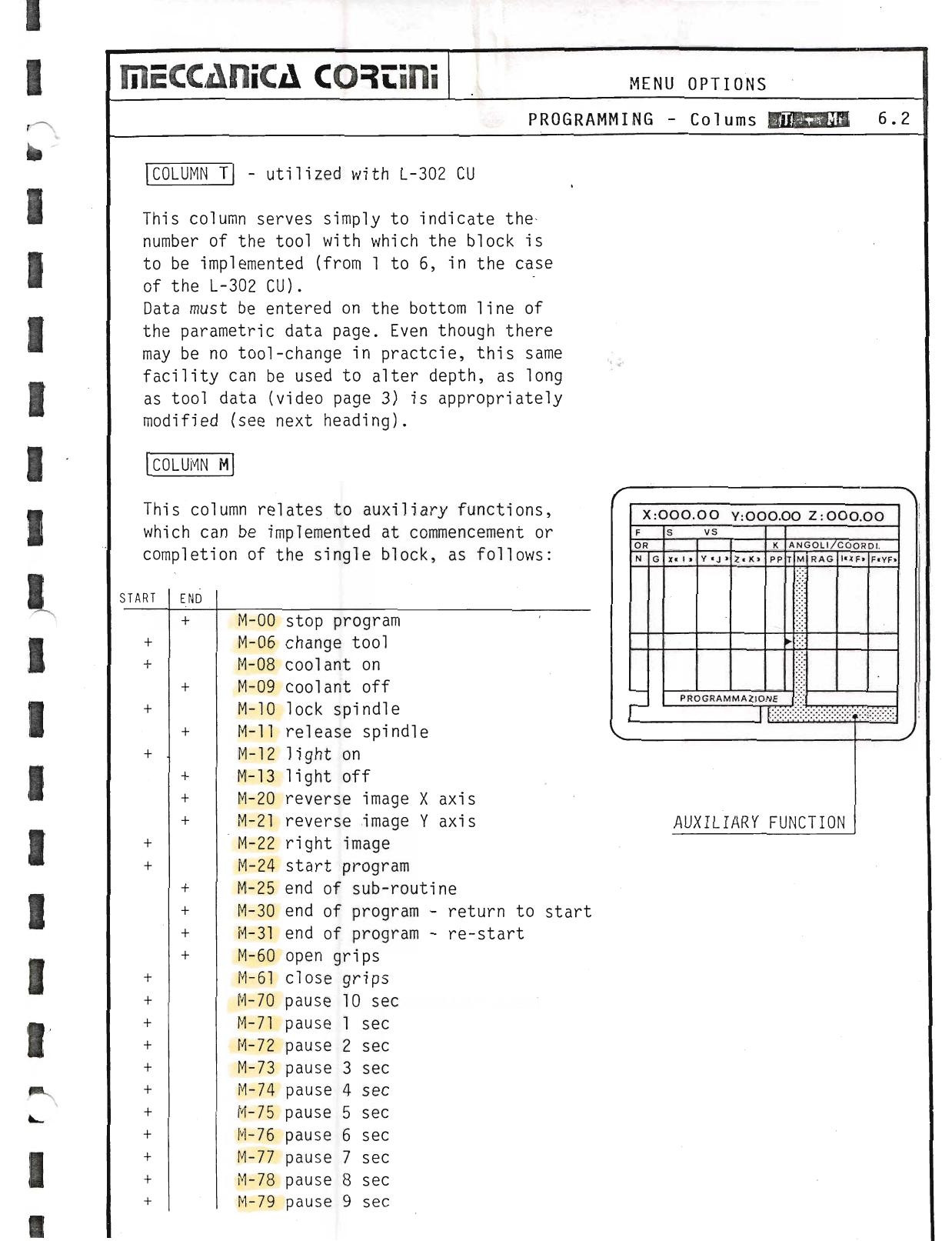
Column T
Utilized with L-302 CU. This column serves simply to indicate the number of the tool with which the block is to be implemented (from 1 to 6, in the case of the L-302 CU). Data must be entered on the bottom line of the parametric data page. Even though there may be no tool-change in practice, this same facility can be used to alter depth, as long as tool data (video page 3) is appropriately modified.
Column M & M-Functions
This column relates to auxiliary functions, which can be implemented at commencement or completion of the single block, as follows:
| START | END | Code | Function |
|---|
| + | | M-00 | Stop program |
| + | | M-06 | Change tool |
| + | + | M-08 | Coolant on |
| + | + | M-09 | Coolant off |
| + | + | M-10 | Lock spindle (proceed) |
| + | + | M-11 | Release spindle |
| + | M-12 | Light on |
| + | + | M-13 | Light off |
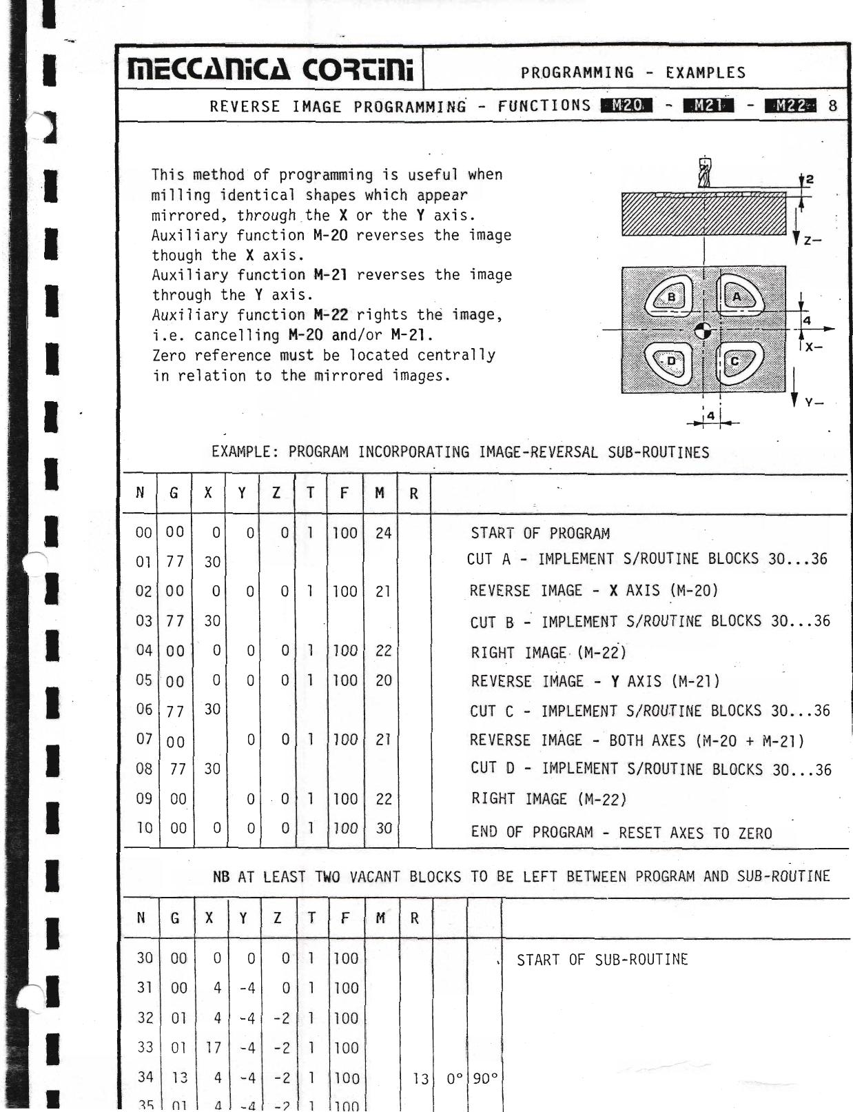
| + | + | M-20 | Reverse image X axis |
| + | + | M-21 | Reverse image Y axis |
| + | + | M-22 | Right image |
| + | | M-24 | Start program |
| + | | M-25 | End of sub-routine |
| + | | M-30 | End of program — return to start |
| + | | M-31 | End of program — re-start |
| + | | M-60 | Open grips |
| + | | M-61 | Close grips |
| + | | M-70 | Pause 10 sec |
| + | | M-71 | Pause 1 sec |
| + | | M-72 | Pause 2 sec |
| + | | M-73 | Pause 3 sec |
| + | | M-74 | Pause 4 sec |
| + | | M-75 | Pause 5 sec |
| + | | M-76 | Pause 6 sec |
| + | | M-77 | Pause 7 sec |
| + | | M-78 | Pause 8 sec |
| + | | M-79 | Pause 9 sec |
▶ Source — Page 053
![Original scan page 053]()
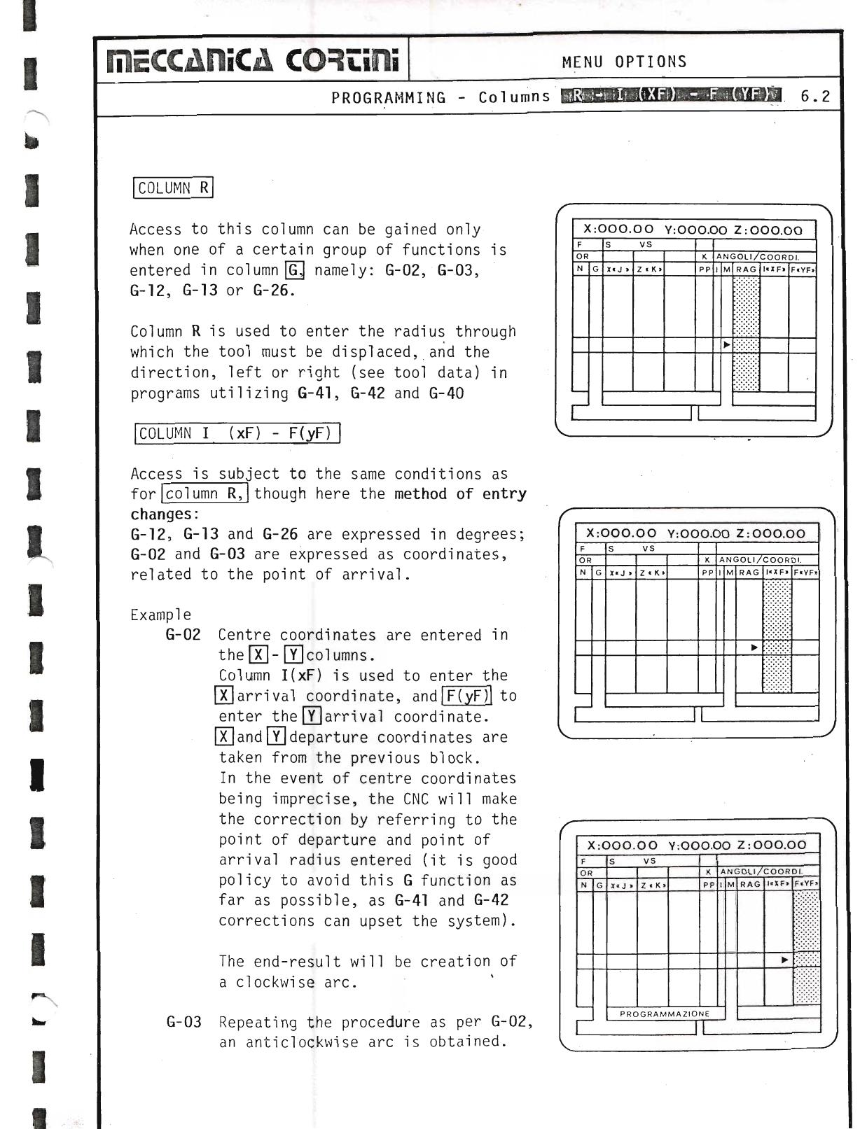
Column R
Access to this column can be gained only when one of a certain group of functions is entered in column G, namely: G-02, G-03, G-12, G-13 and G-26. Column R is used to enter the radius through which the tool must be displaced, and the direction, left or right (see tool data) in programs utilizing G-41, G-42 and G-40.
Column I(xF) / F(yF)
Access is subject to the same conditions as for column R, though here the method of entry changes:
- G-12, G-13 and G-26 are expressed in degrees;
- G-02 and G-03 are expressed as coordinates, related to the point of arrival.
G-02 — Centre coordinates are entered in the X–Y columns. Column I(xF) is used to enter the X arrival coordinate, and F(yF) to enter the Y arrival coordinate. X and Y departure coordinates are taken from the previous block. In the event of centre coordinates being imprecise, the CNC will make the correction by referring to the point of departure and point of arrival radius entered. The end-result will be creation of a clockwise arc.
G-03 — Repeating the procedure as per G-02, an anticlockwise arc is obtained.
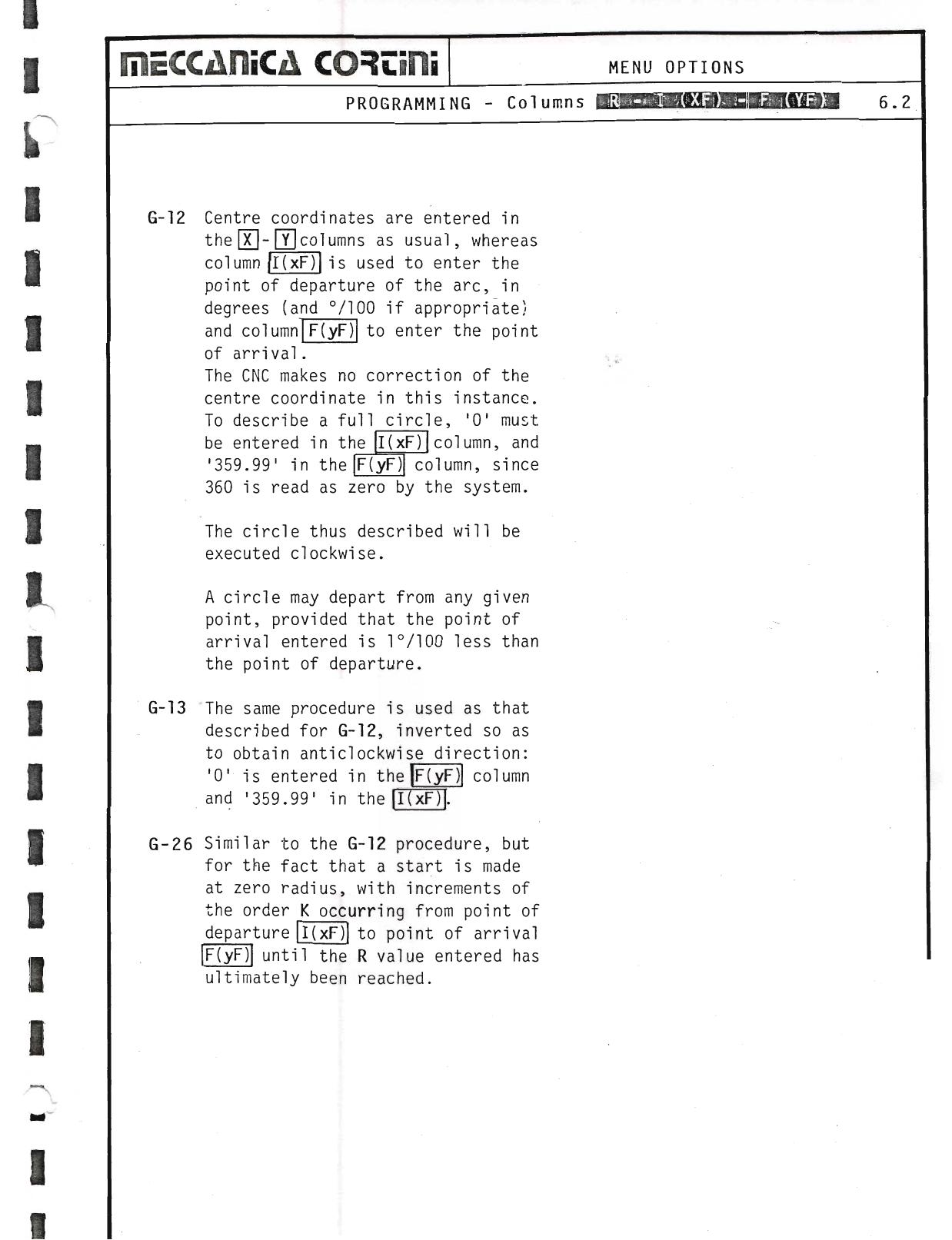
G-12 — Centre coordinates are entered in the X–Y columns as usual, whereas column I(xF) is used to enter the point of departure of the arc in degrees (and °/100 if appropriate), and column F(yF) to enter the point of arrival. The CNC makes no correction of the centre coordinate in this instance. To describe a full circle, '0' must be entered in the I(xF) column and '359.99' in the F(yF) column, since 360 is read as zero by the system. The circle thus described will be executed clockwise. A circle may depart from any given point, provided that the point of arrival entered is 1°/100 less than the point of departure.
G-13 — The same procedure is used as that described for G-12, inverted so as to obtain anticlockwise direction: '0' is entered in the F(yF) column and '359.99' in the I(xF) column.
G-26 — Similar to the G-12 procedure, but for the fact that a start is made at zero radius, with increments of the order K occurring from point of departure to point of arrival until the R value entered has ultimately been reached.
▶ Source — Page 054
![Original scan page 054]()
▶ Source — Page 055
![Original scan page 055]()
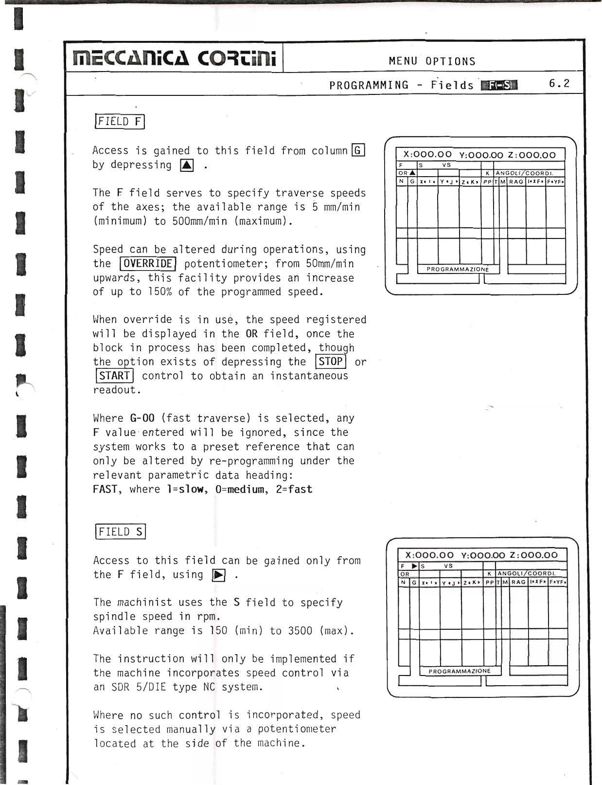
Field F
Access is gained to this field from column G by depressing ↓. The F field serves to specify traverse speeds of the axes; the available range is 5 mm/min (minimum) to 500 mm/min (maximum).
Speed can be altered during operations, using the OVERRIDE potentiometer; from 50 mm/min upwards, this facility provides an increase of up to 150% of the programmed speed. When override is in use, the speed registered will be displayed in the OR field, once the block in process has been completed, though the option exists of depressing STOP or START to obtain an instantaneous readout.
Where G-00 (fast traverse) is selected, any F value entered will be ignored, since the system works to a preset reference that can only be altered by re-programming under the relevant parametric data heading: FAST, where 1 = slow, 0 = medium, 2 = fast.
Field S
Access to this field can be gained only from the F field, using →. The machinist uses the S field to specify spindle speed in rpm. Available range is 150 (min) to 3500 (max). The instruction will only be implemented if the machine incorporates speed control via an SDR 5/DIE type NC system. Where no such control is incorporated, speed is selected manually via a potentiometer located at the side of the machine.
▶ Source — Page 056
![Original scan page 056]()
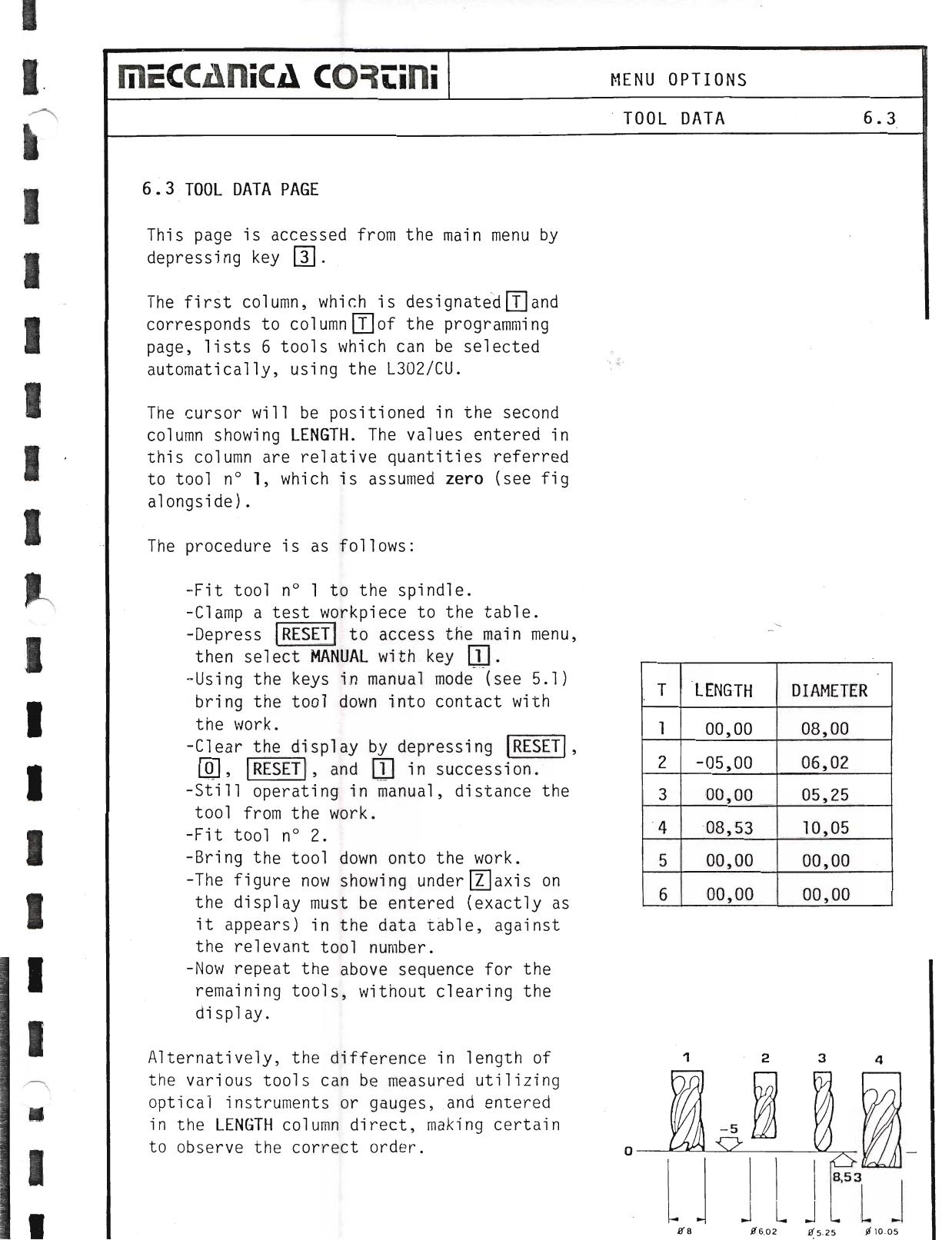
This page is accessed from the main menu by depressing key 3. The first column, which is designated T and corresponds to column T of the programming page, lists 6 tools which can be selected automatically, using the L302/CU.
The cursor will be positioned in the second column showing LENGTH. The values entered in this column are relative quantities referred to tool no. 1, which is assumed zero.
The procedure is as follows:
- Fit tool no. 1 to the spindle.
- Clamp a test workpiece to the table.
- Depress RESET to access the main menu, then select MANUAL with key 1.
- Using the keys in manual mode, bring the tool down into contact with the work.
- Clear the display by depressing RESET, 0, RESET, and 1 in succession.
- Still operating in manual, distance the tool from the work.
- Fit tool no. 2.
- Bring the tool down onto the work.
- The figure now showing under Z axis on the display must be entered (exactly as it appears) in the data table, against the relevant tool number.
- Repeat the above sequence for the remaining tools, without clearing the display.
Alternatively, the difference in length of the various tools can be measured utilizing optical instruments or gauges, and entered in the LENGTH column direct, making certain to observe the correct order.
The third column is headed DIAMETER. In this instance, the machinist simply enters the diameter of each tool as measured with a micrometer. Tool length is acknowledged automatically by the CNC, whereas diameter must be qualified by using the G-41 and G-42 instructions to specify right and left, respectively.
▶ Source — Page 057
![Original scan page 057]()
▶ Source — Page 058
![Original scan page 058]()
6.4 Program Load from Magnetic Tape
Before loading pre-recorded program data, it is good policy to clear any blocks currently stored in the CNC's random access memory by depressing * then MC, whereupon the menu will read out "MEMORY M".
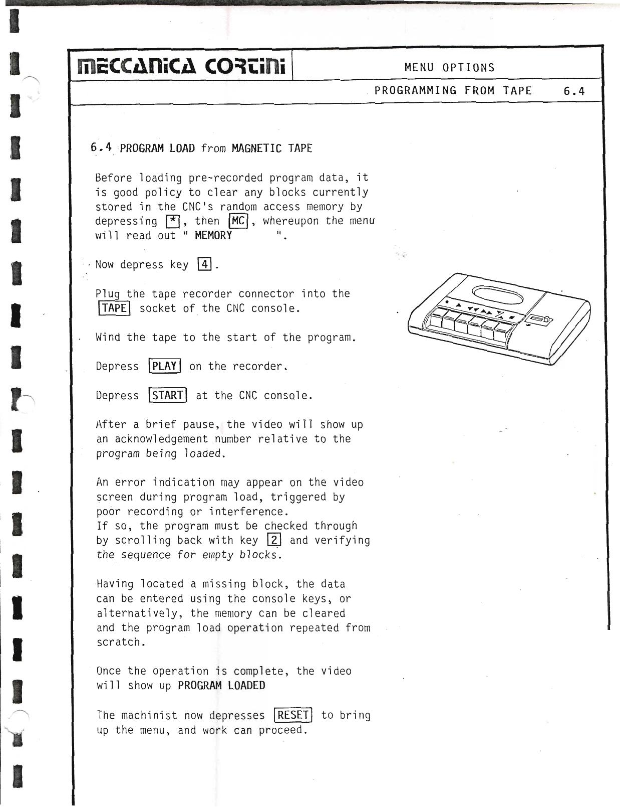
Now depress key 4. Plug the tape recorder connector into the TAPE socket of the CNC console. Wind the tape to the start of the program. Depress PLAY on the recorder. Depress START at the CNC console.
After a brief pause, the video will show up an acknowledgement number relative to the program being loaded. An error indication may appear on the video screen during program load, triggered by poor recording or interference. If so, the program must be checked through by scrolling back with key ↑ and verifying the sequence for empty blocks. Having located a missing block, the data can be entered using the console keys, or alternatively, the memory can be cleared and the program load operation repeated from scratch.
Once the operation is complete, the video will show up PROGRAM LOADED. The machinist now depresses RESET to bring up the menu, and work can proceed.
▶ Source — Page 059
![Original scan page 059]()
6.5 Recording from CNC onto Tape
Departing from the menu, depress key 5. Compile details in order to enable transfer of the data stored in the CNC memory onto magnetic tape:
- Directory number: four digits, which provide the program address; confirm by depressing ENTER.
- Start number: the number of the first block of the overall program; confirm by depressing ENTER.
- Finish number: the number of the last block; confirm by depressing ENTER.
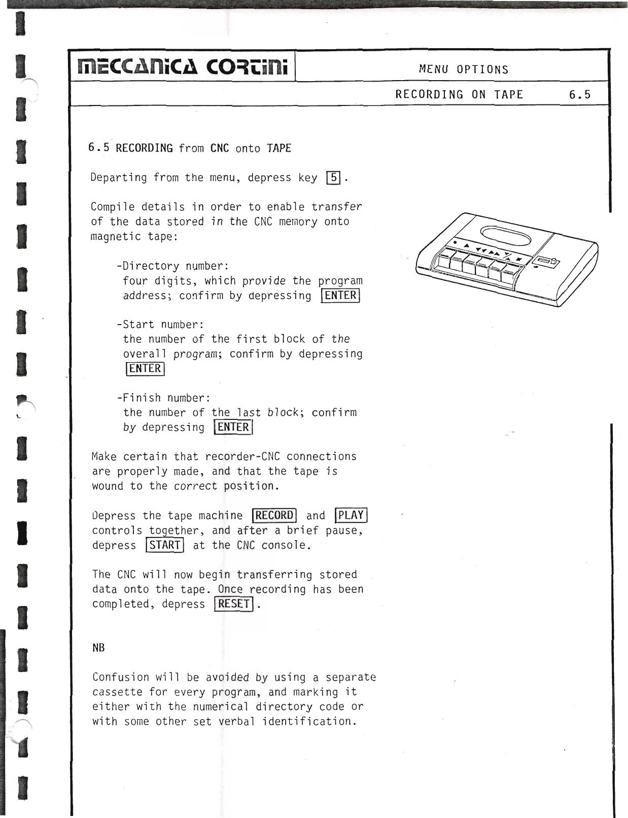
Make certain that recorder-CNC connections are properly made, and that the tape is wound to the correct position. Depress the tape machine RECORD and PLAY controls together, and after a brief pause, depress START at the CNC console. The CNC will now begin transferring stored data onto the tape. Once recording has been completed, depress RESET.
NB — Confusion will be avoided by using a separate cassette for every program, and marking it either with the numerical directory code or with some other set verbal identification.
▶ Source — Page 060
![Original scan page 060]()
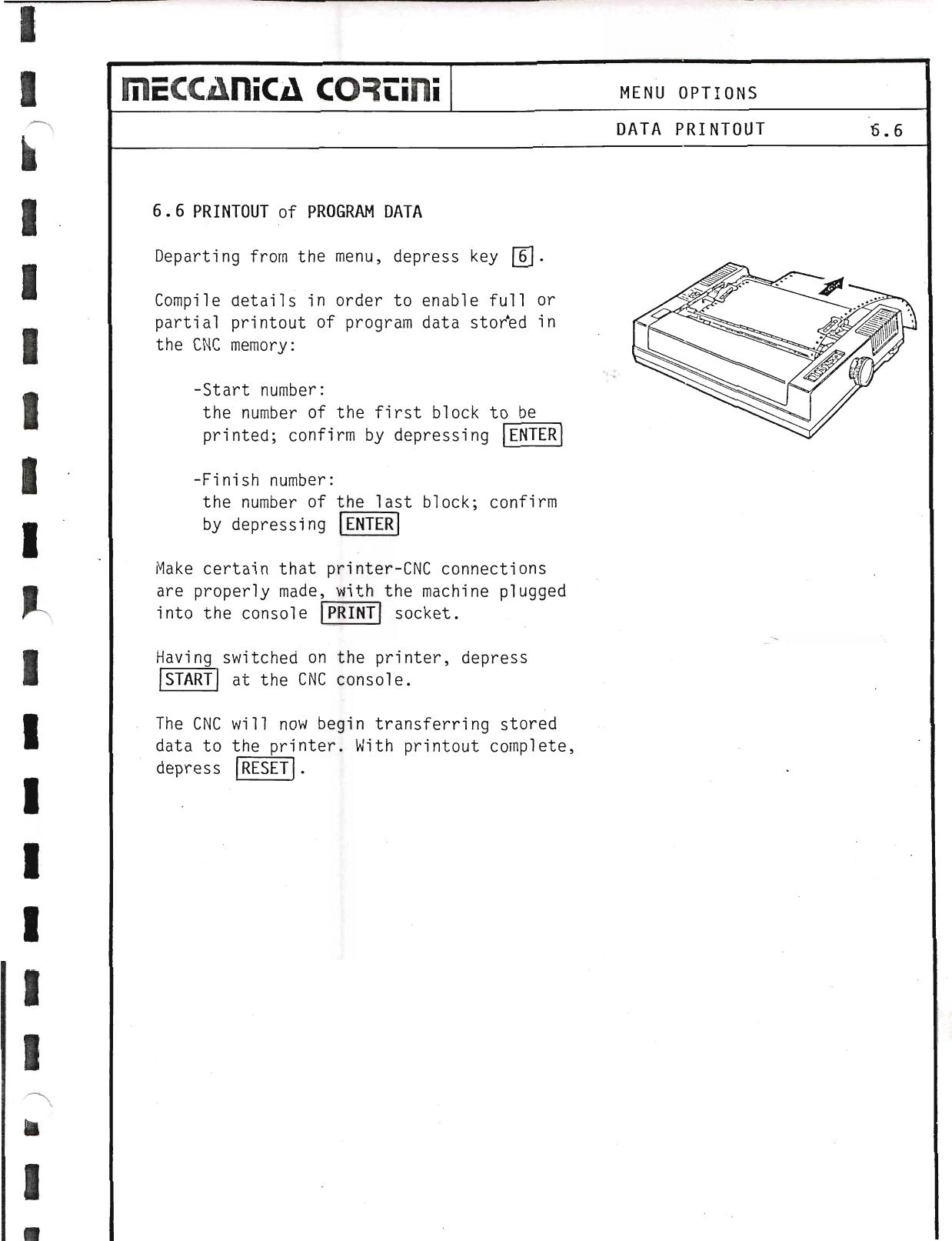
6.6 Printout of Program Data
Departing from the menu, depress key 6. Compile details in order to enable full or partial printout of program data stored in the CNC memory:
- Start number: the number of the first block to be printed; confirm by depressing ENTER.
- Finish number: the number of the last block; confirm by depressing ENTER.
Make certain that printer-CNC connections are properly made, with the machine plugged into the console PRINT socket. Having switched on the printer, depress START at the CNC console. The CNC will now begin transferring stored data to the printer. With printout complete, depress RESET.
▶ Source — Page 061
![Original scan page 061]()
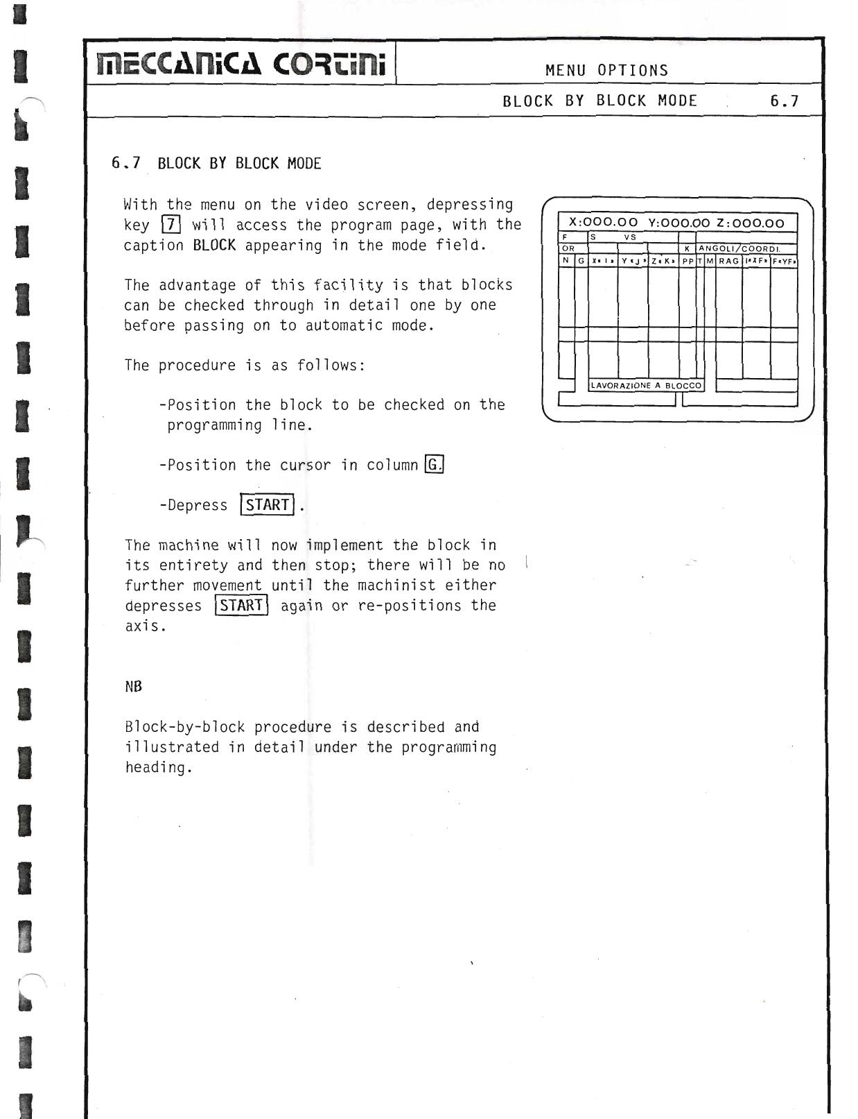
6.7 Block by Block Mode
With the menu on the video screen, depressing key 7 will access the program page, with the caption BLOCK appearing in the mode field.
The advantage of this facility is that blocks can be checked through in detail one by one before passing on to automatic mode. The procedure is as follows:
- Position the block to be checked on the programming line.
- Position the cursor in column G.
- Depress START.
The machine will now implement the block in its entirety and then stop; there will be no further movement until the machinist either depresses START again or re-positions the axis.
NB — Block-by-block procedure is described and illustrated in detail under the programming heading.
▶ Source — Page 062
![Original scan page 062]()
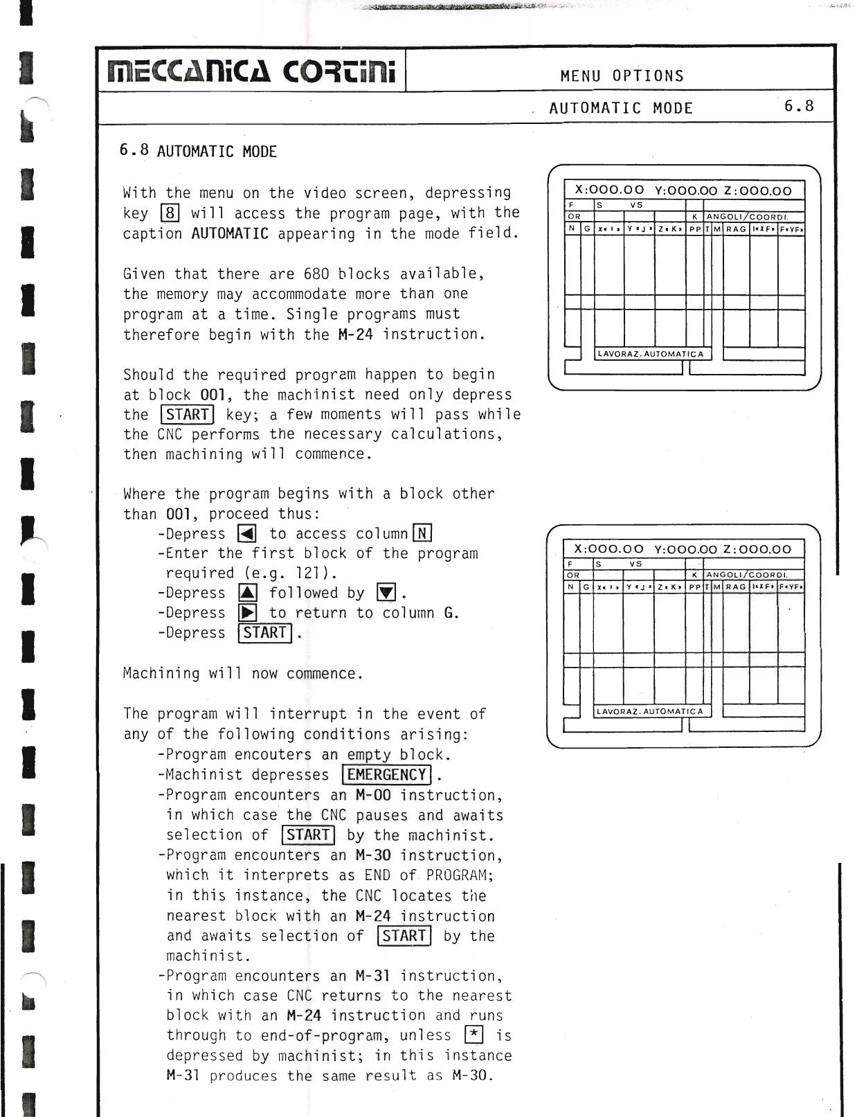
6.8 Automatic Mode
With the menu on the video screen, depressing key 8 will access the program page, with the caption AUTOMATIC appearing in the mode field.
Given that there are 680 blocks available, the memory may accommodate more than one program at a time. Single programs must therefore begin with the M-24 instruction.
Should the required program happen to begin at block 001, the machinist need only depress the START key; a few moments will pass while the CNC performs the necessary calculations, then machining will commence.
Where the program begins with a block other than 001, proceed thus:
- Depress N to access column N.
- Enter the first block of the program required (e.g. 121).
- Depress ↑ followed by ↓.
- Depress G to return to column G.
- Depress START.
Machining will now commence. The program will interrupt in the event of any of the following conditions arising:
- Program encounters an empty block.
- Machinist depresses EMERGENCY.
- Program encounters an M-00 instruction, in which case the CNC pauses and awaits selection of START by the machinist.
- Program encounters an M-30 instruction, which it interprets as END of PROGRAM; in this instance, the CNC locates the nearest block with an M-24 instruction and awaits selection of START by the machinist.
- Program encounters an M-31 instruction, in which case CNC returns to the nearest block with an M-24 instruction and runs through to end-of-program, unless STOP is depressed by machinist; in this instance M-31 produces the same result as M-30.
▶ Source — Page 063
![Original scan page 063]()
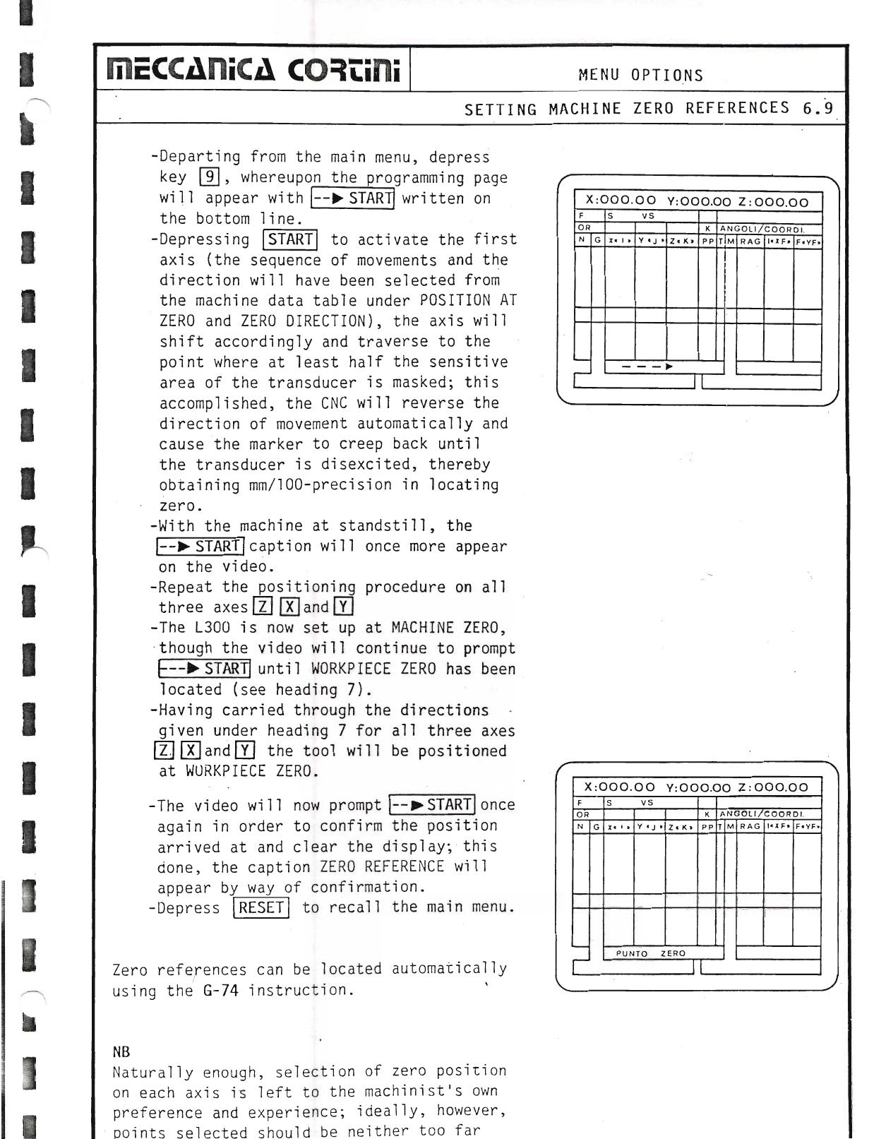
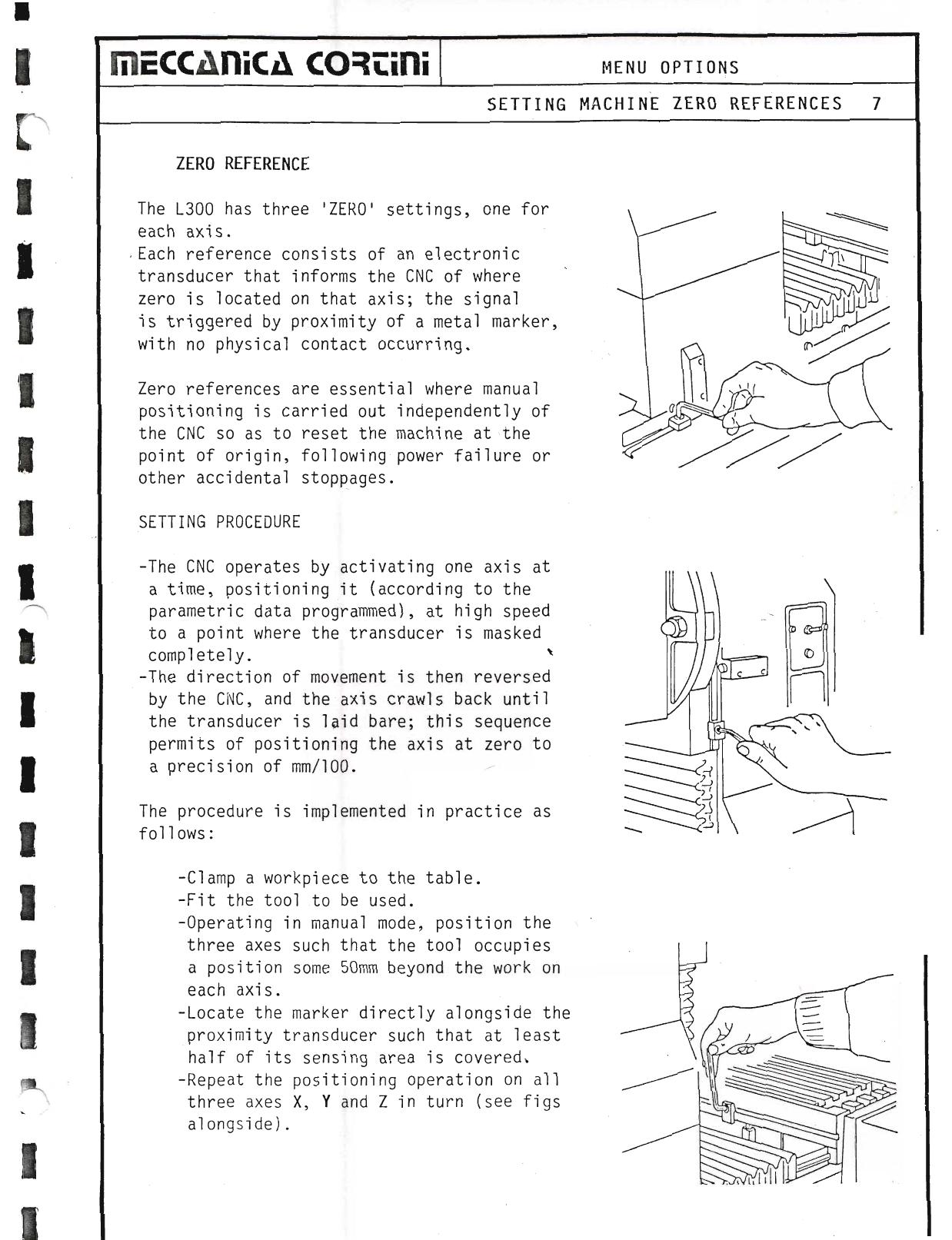
6.9 Setting Machine Zero References
Departing from the main menu, depress key 9, whereupon the programming page will appear.
Depressing START to activate the first axis (the sequence of movements and the direction will have been selected from the machine data table under POSITION AT ZERO and ZERO DIRECTION), the axis will shift accordingly and traverse to the point where at least half the sensitive area of the transducer is masked; this accomplished, the CNC will reverse the direction of movement automatically and cause the marker to creep back until the transducer is disexcited, thereby obtaining mm/100-precision in locating zero.
With the machine at standstill, the → START caption will once more appear on the video. Repeat the positioning procedure on all three axes Z, K and Y. The L300 is now set up at MACHINE ZERO, though the video will continue to prompt until WORKPIECE ZERO has been located (see heading 7).
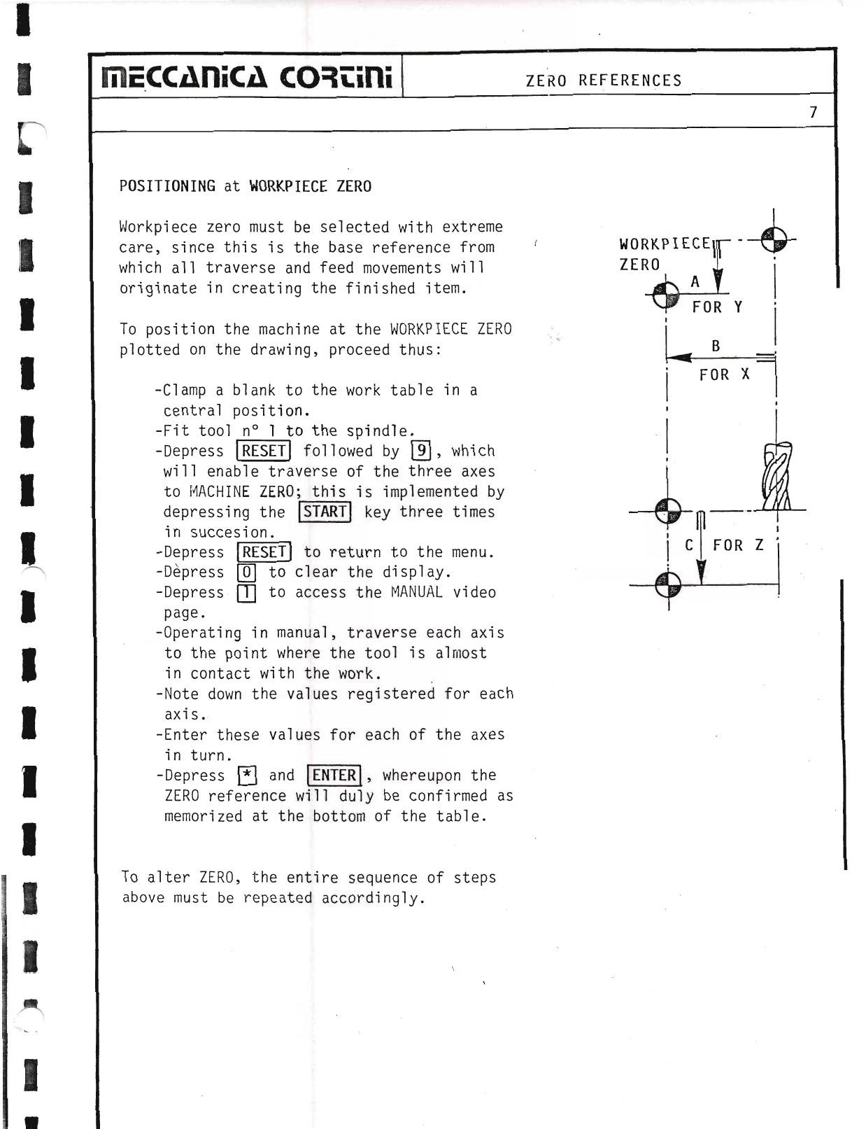
Having carried through the directions given under heading 7 for all three axes Z, K and Y, the tool will be positioned at WORKPIECE ZERO. The video will now prompt → START once again in order to confirm the position arrived at and clear the display; this done, the caption ZERO REFERENCE will appear by way of confirmation. Depress RESET to recall the main menu.
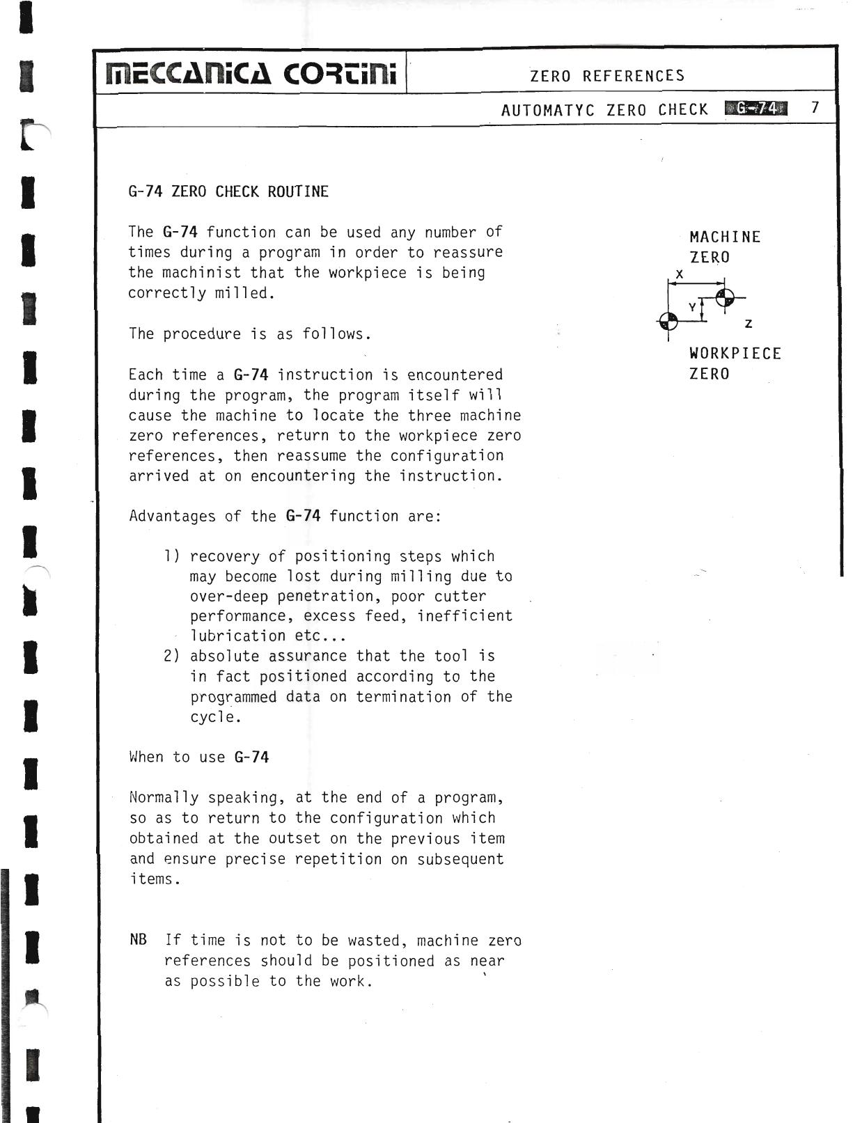
Zero references can be located automatically using the G-74 instruction.
NB — Naturally enough, selection of zero position on each axis is left to the machinist's own preference and experience; ideally, however, the points selected should be neither too far from nor too close to the work.
▶ Source — Page 064
![Original scan page 064]()
6.*0 Memory Check
This facility enables verification of the efficiency of the system's random access memory. The following data must appear:
- BLOCKS: 680 — no. of lines available
- V.-5.12c — type of system installed
- 86.09.11 — last system update
▶ Source — Page 065
![Original scan page 065]()
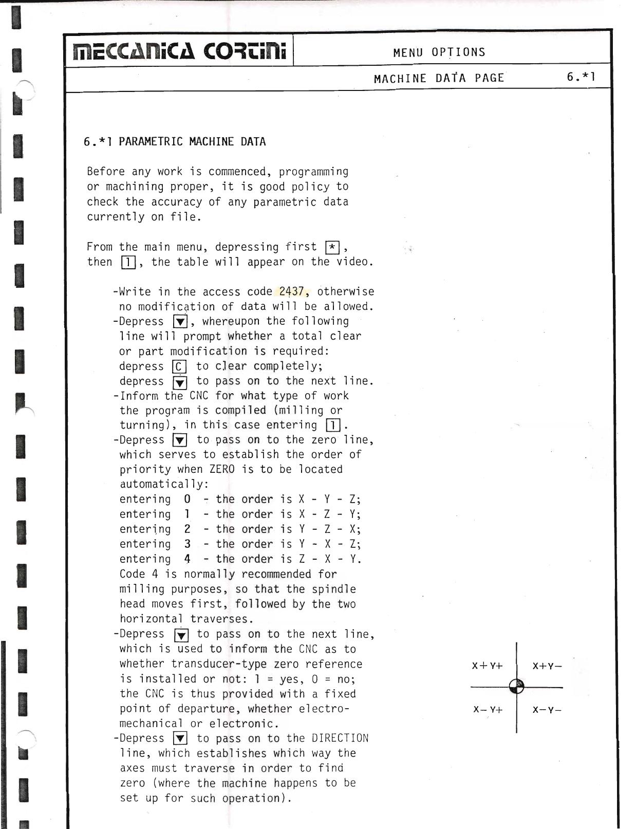
6.*1 Parametric Machine Data
Before any work is commenced, programming or machining proper, it is good policy to check the accuracy of any parametric data currently on file.
From the main menu, depressing first * then 1, the table will appear on the video.
- Write in the access code 2437, otherwise no modification of data will be allowed.
- Depress ↓, whereupon the following line will prompt whether a total clear or part modification is required: depress N to clear completely; depress ↓ to pass on to the next line.
- Inform the CNC for what type of work the program is compiled (milling or turning): enter 1 for milling.
- Depress ↓ to pass on to the zero line, which serves to establish the order of priority when ZERO is to be located automatically:
- entering 0 — the order is X–Y–Z
- entering 1 — the order is X–Z–Y
- entering 2 — the order is Y–Z–X
- entering 3 — the order is Y–X–Z
- entering 4 — the order is Z–X–Y
Code 4 is normally recommended for milling purposes, so that the spindle head moves first, followed by the two horizontal traverses.
- Depress ↓ to pass on to the next line, which is used to inform the CNC as to whether transducer-type zero reference is installed or not: 1 = yes, 0 = no.
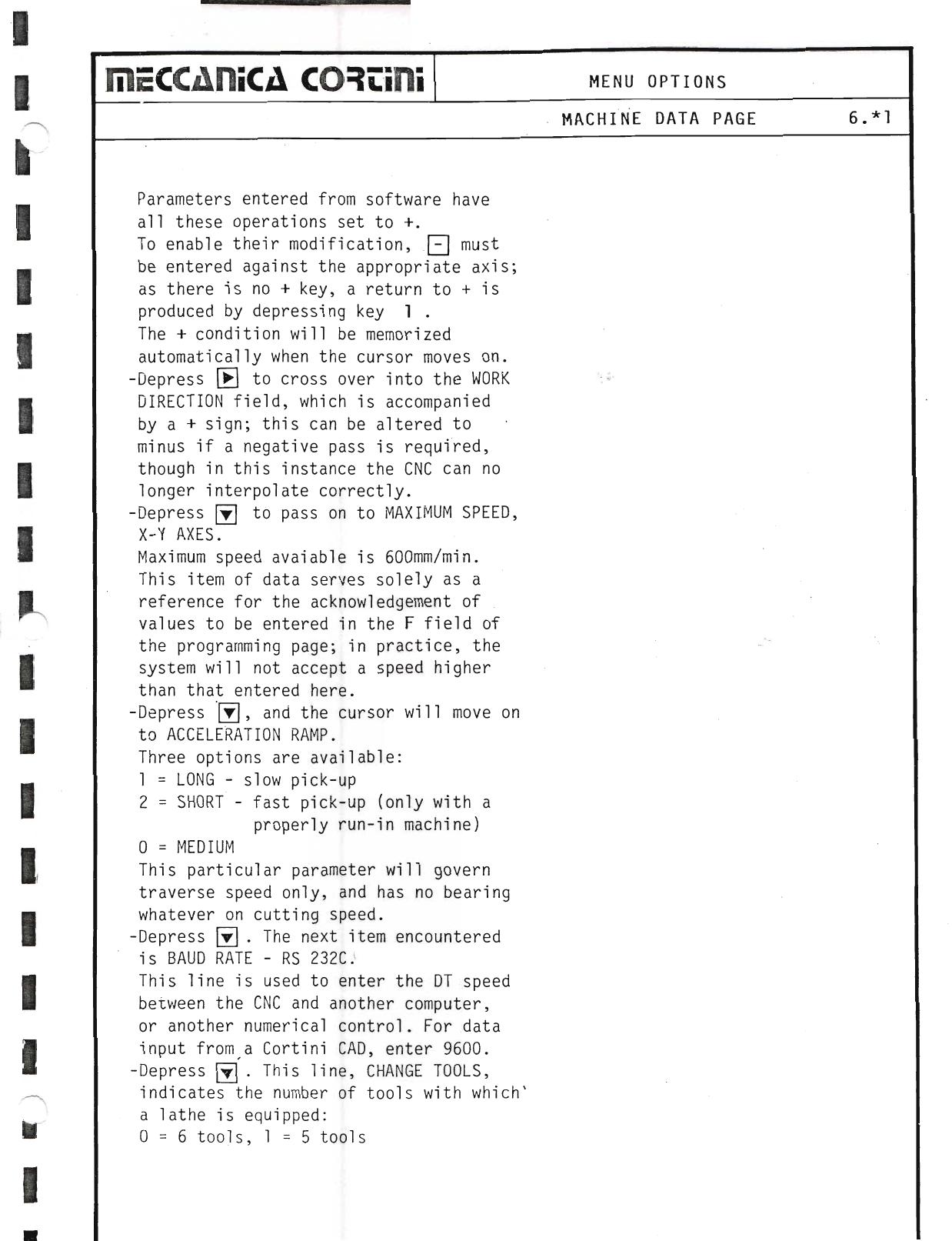
- Depress ↓ to pass on to the DIRECTION line, which establishes which way the axes must traverse in order to find zero. Parameters entered from software have all these operations set to +. To enable their modification, − must be entered against the appropriate axis; a return to + is produced by depressing key 1.
- Depress → to cross over into the WORK DIRECTION field; this can be altered to minus if a negative pass is required, though in this instance the CNC can no longer interpolate correctly.
- Depress ↓ to pass on to MAXIMUM SPEED, X–Y AXES. Maximum speed available is 600 mm/min. In practice, the system will not accept a speed higher than that entered here.
- Depress ↓, and the cursor will move on to ACCELERATION RAMP. Three options: 1 = LONG (slow pick-up), 2 = SHORT (fast pick-up, only with a properly run-in machine), 0 = MEDIUM. This parameter governs traverse speed only.
- Depress ↓. The next item is BAUD RATE – RS 232C. This line is used to enter the DT speed between the CNC and another computer. For data input from a Cortini CAD, enter 9600.
- Depress ↓. CHANGE TOOLS indicates the number of tools with which a lathe is equipped: 0 = 6 tools, 1 = 5 tools.
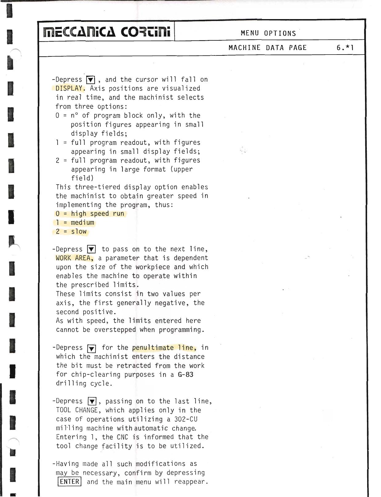
- Depress ↓, and the cursor will fall on DISPLAY. Axis positions are visualized in real time; three options: 0 = block number only (figures in small display fields; high speed run), 1 = full program readout (small display fields; medium speed), 2 = full program readout in large format (upper field; slow speed).
- Depress ↓ to pass on to the next line, WORK AREA, a parameter that is dependent upon the size of the workpiece and which enables the machine to operate within the prescribed limits. These limits consist in two values per axis, the first generally negative, the second positive.
- Depress ↓ for the penultimate line: enter the distance the bit must be retracted from the work for chip-clearing purposes in a G-83 drilling cycle.
- Depress ↓, passing on to the last line, TOOL CHANGE, which applies only in the case of operations utilizing a 302-CU milling machine with automatic change. Entering 1, the CNC is informed that the tool change facility is to be utilized.
- Having made all such modifications as may be necessary, confirm by depressing ENTER and the main menu will reappear.
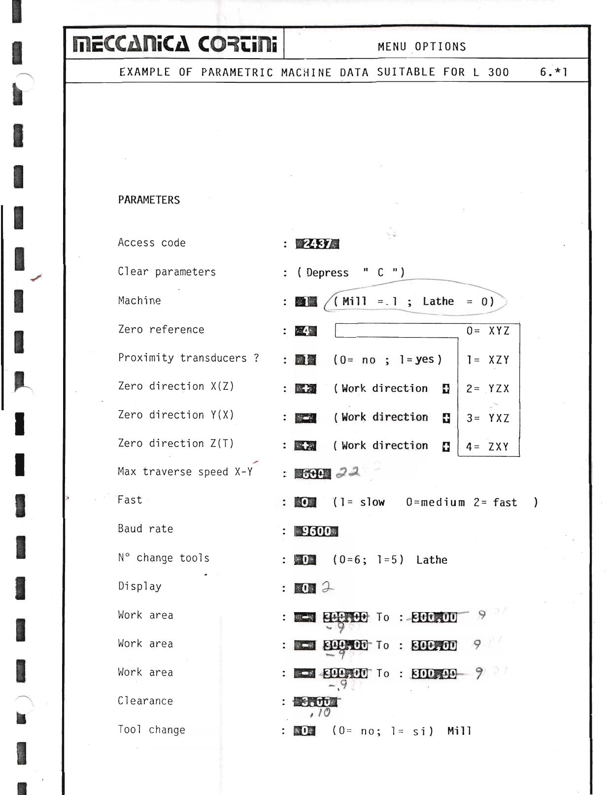
Example: Parametric Machine Data Table (L300)
| Parameter | Example Value / Options |
|---|
| Access code | 2437 |
| Clear parameters | Depress CN |
| Machine | BM (Mill = 1, Lathe = 0) |
| Zero reference | ZS 0 = XYZ |
| Proximity transducers? | ER (0 = no; 1 = yes) — 1 = XZY |
| Zero direction X(Z) | EQH (Work direction) — 2 = YZX |
| Zero direction Y(X) | Bem (Work direction) — 3 = YXZ |
| Zero direction Z(T) | (Work direction) — 4 = ZXY |
| Max traverse speed X–Y | op |
| Fast (acceleration ramp) | BOM (1 = slow, 0 = medium, 2 = fast) |
| Baud rate | — |
| No. change tools | GN (0 = 6; 1 = 5) — Lathe |
| Display | eo |
| Work area 1 | eer To: Eee |
| Work area 2 | Ea To: EER |
| Work area 3 | ER To: Een |
| Clearance Z | — |
| Tool change | BOB (0 = no; 1 = si) — Mill |
▶ Source — Page 066
![Original scan page 066]()
▶ Source — Page 067
![Original scan page 067]()
▶ Source — Page 068
![Original scan page 068]()
▶ Source — Page 069
![Original scan page 069]()
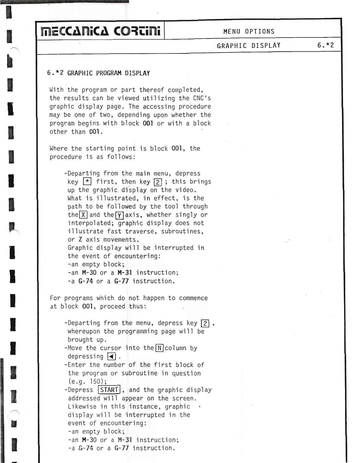
6.*2 Graphic Program Display
With the program or part thereof completed, the results can be viewed utilizing the CNC's graphic display page. The accessing procedure may be one of two, depending upon whether the program begins with block 001 or with a block other than 001.
Where the starting point is block 001:
- Departing from the main menu, depress key * first, then key 2; this brings up the graphic display on the video.
What is illustrated, in effect, is the path to be followed by the tool through the X and the Y axis, whether singly or interpolated; graphic display does not illustrate fast traverse, subroutines, or Z axis movements.
Graphic display will be interrupted in the event of encountering: an empty block; an M-30 or a M-31 instruction; a G-74 or a G-77 instruction.
For programs which do not happen to commence at block 001:
- Departing from the menu, depress key →, whereupon the programming page will be brought up.
- Move the cursor into the N column by depressing N.
- Enter the number of the first block of the program or subroutine in question (e.g. 150).
- Depress START, and the graphic display addressed will appear on the screen.
Likewise in this instance, graphic display will be interrupted in the event of encountering: an empty block; an M-30 or a M-31 instruction; a G-74 or a G-77 instruction.
▶ Source — Page 070
![Original scan page 070]()
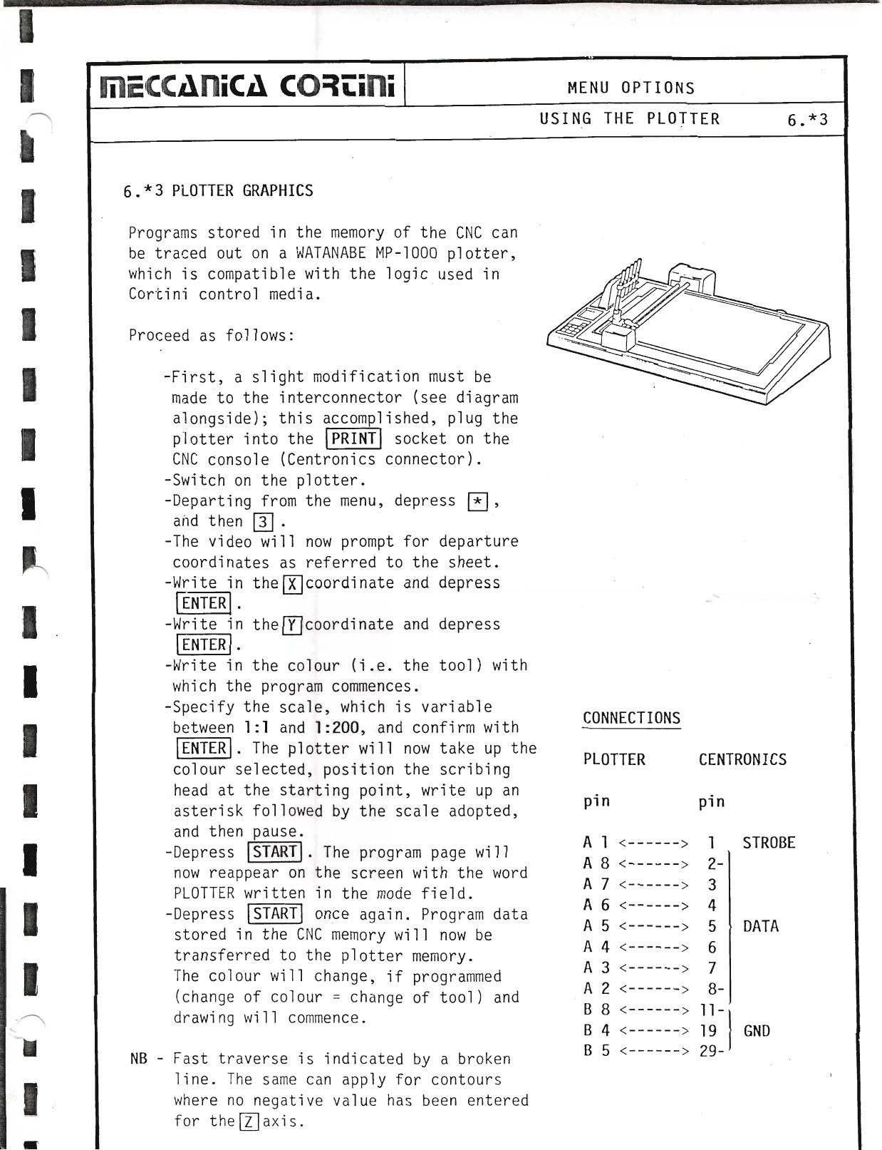
6.*3 Plotter Graphics
Programs stored in the memory of the CNC can be traced out on a WATANABE MP-1000 plotter, which is compatible with the logic used in Cortini control media.
Proceed as follows:
- A slight modification must be made to the interconnector (see diagram); this accomplished, plug the plotter into the socket on the CNC console (Centronics connector).
- Switch on the plotter.
- Departing from the menu, depress * then 3.
- The video will now prompt for departure coordinates as referred to the sheet.
- Write in the X coordinate and depress ENTER.
- Write in the Y coordinate and depress ENTER.
- Write in the colour (i.e. the tool) with which the program commences.
- Specify the scale, which is variable between 1:1 and 1:200, and confirm with ENTER. The plotter will now take up the colour selected, position the scribing head at the starting point, write up an asterisk followed by the scale adopted, and then pause.
- Depress START. The program page will now reappear on the screen with the word PLOTTER written in the mode field.
- Depress START once again. Program data stored in the CNC memory will now be transferred to the plotter memory. The colour will change, if programmed (change of colour = change of tool) and drawing will commence.
NB — Fast traverse is indicated by a broken line. The same can apply for contours where no negative value has been entered for the Z axis.
Plotter Connections (Centronics)
| Plotter pin | CNC pin | Signal |
|---|
| 1 | 1 | STROBE |
| 2–8 | 2–8 | DATA |
| 6 | 6 | — |
| 7 | 7 | — |
| 8 | 8 | — |
| 19 | 4 | GND |
| 29 | 5 | — |
▶ Source — Page 071
![Original scan page 071]()
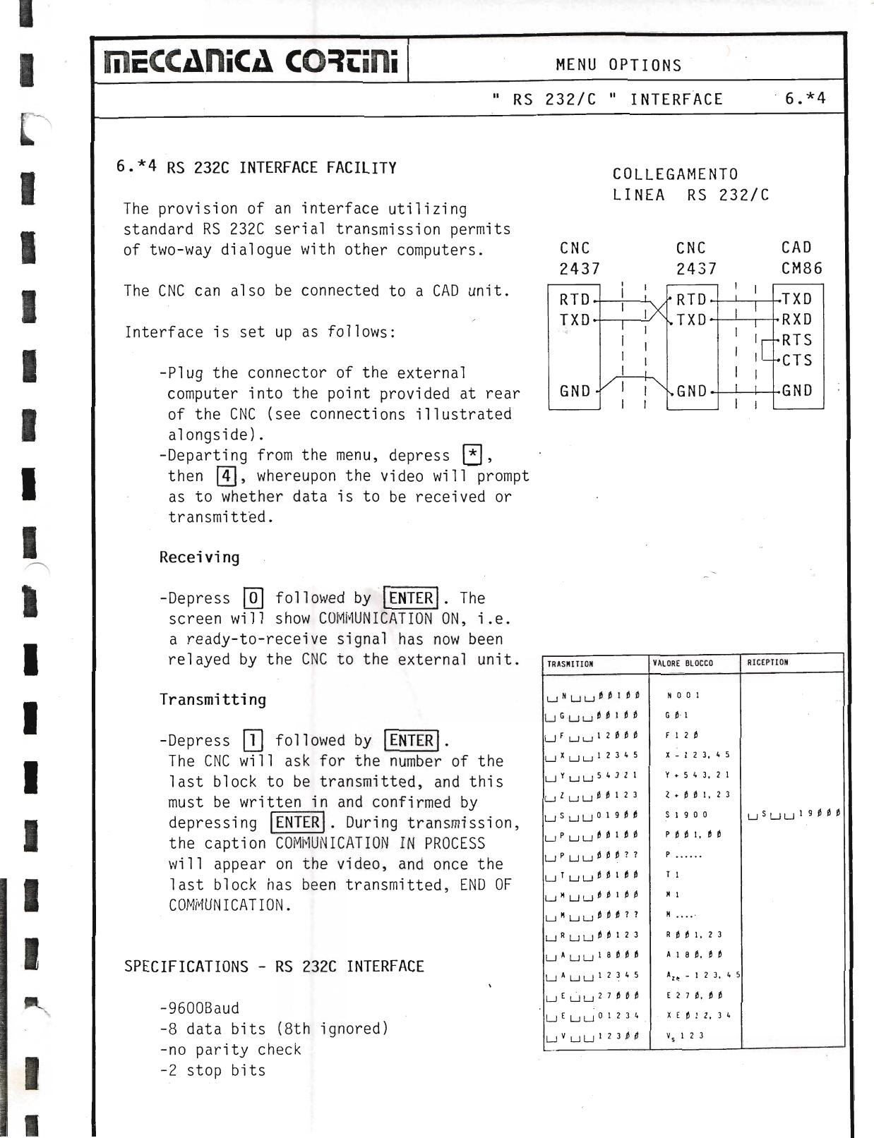
6.*4 RS 232C Interface Facility
The provision of an interface utilizing standard RS 232C serial transmission permits of two-way dialogue with other computers. The CNC can also be connected to a CAD unit.
Interface is set up as follows:
- Plug the connector of the external computer into the point provided at the rear of the CNC (see connections illustrated).
- Departing from the menu, depress * then 4, whereupon the video will prompt as to whether data is to be received or transmitted.
Receiving: Depress 0 followed by ENTER. The screen will show COMMUNICATION ON, i.e. a ready-to-receive signal has now been relayed by the CNC to the external unit.
Transmitting: Depress 1 followed by ENTER. The CNC will ask for the number of the last block to be transmitted, and this must be written in and confirmed by depressing ENTER. During transmission, the caption COMMUNICATION IN PROCESS will appear on the video, and once the last block has been transmitted, END OF COMMUNICATION.
Specifications — RS 232C Interface
▶ Source — Page 072
![Original scan page 072]()